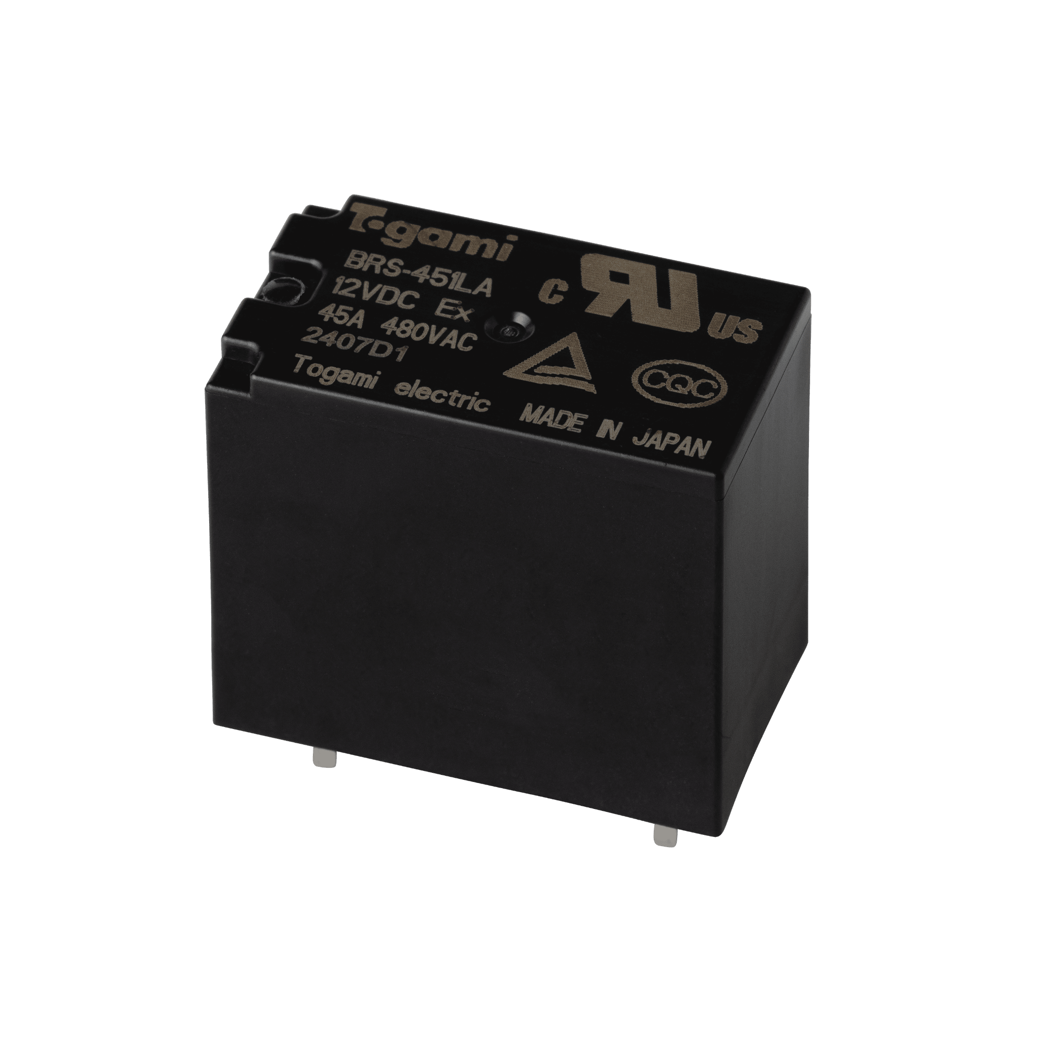
BRS-451LA
Togami Electric Mfg. manufacturers standard electromagnetic contactor/starters, economical electromagnetic contactor/starters, DC-operated electromagnetic contactor/starters, and other types of electromagnetic contactor/starters.
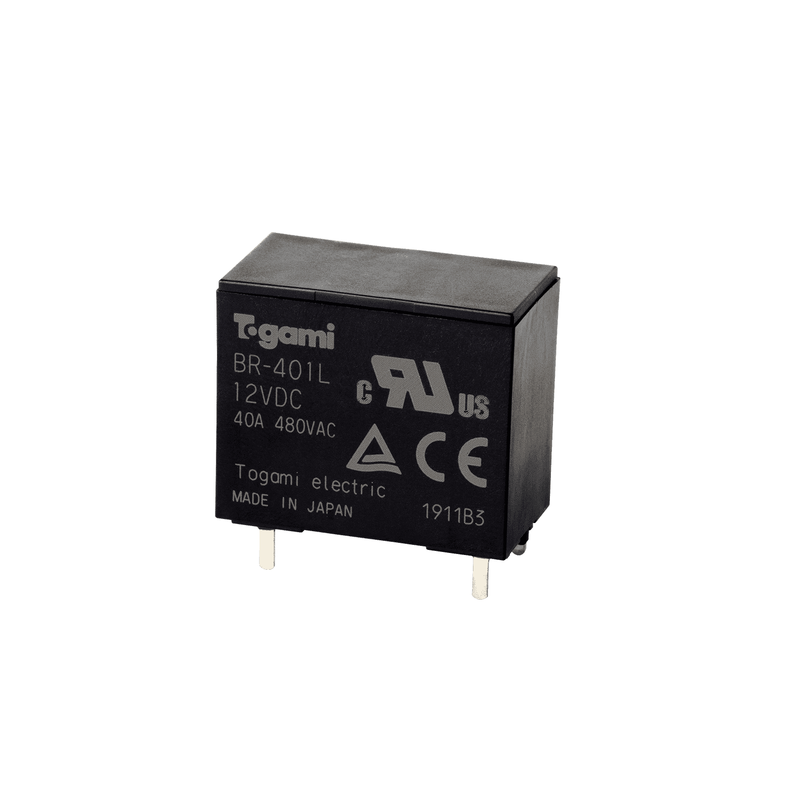
Our extensive lineup includes PCB relays used for inrush current prevention circuits and pre-charge circuits.
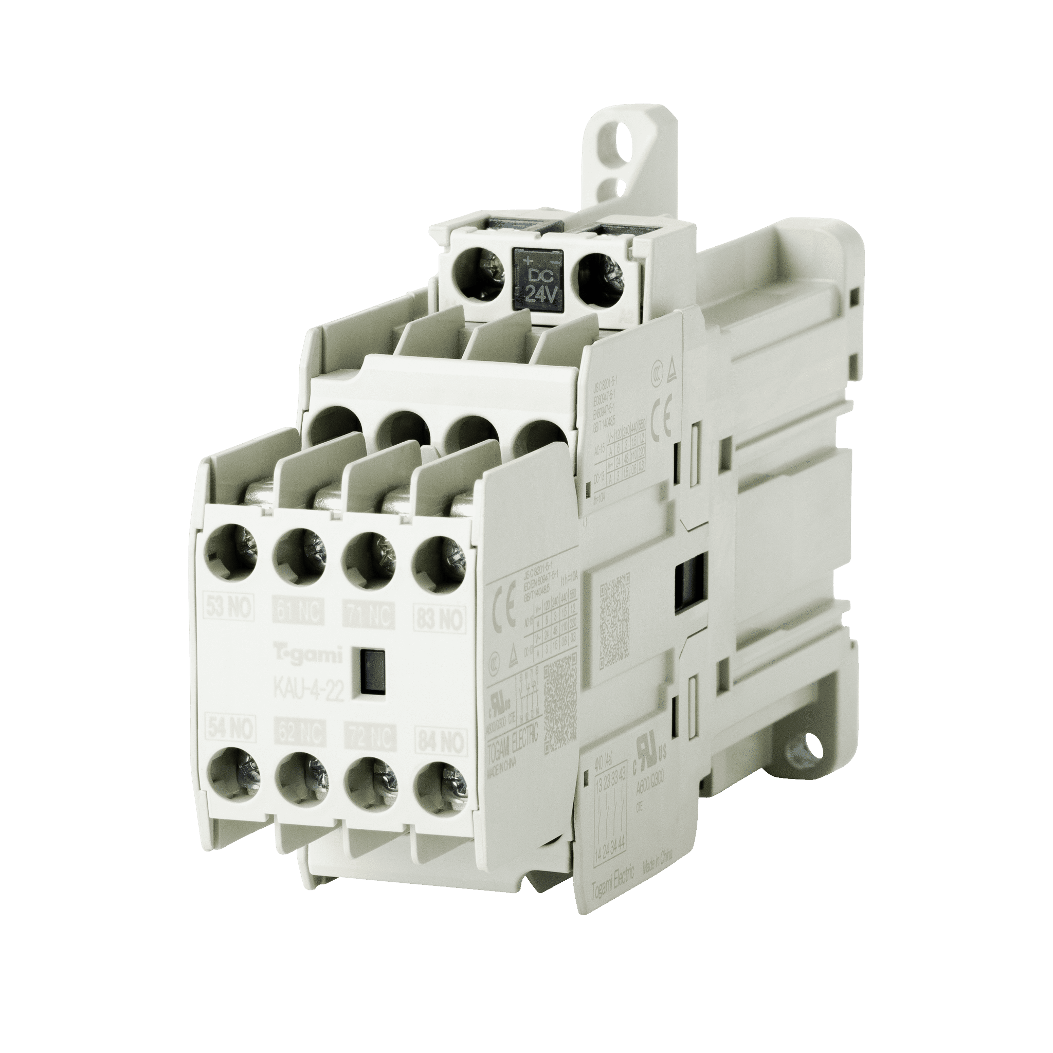
These are units for controlling the switching of equipment, including motors and pumps. They feature a compact design for cost-effectiveness and ease of use, allowing flexible custom designs combining the functions required to meet customer needs.
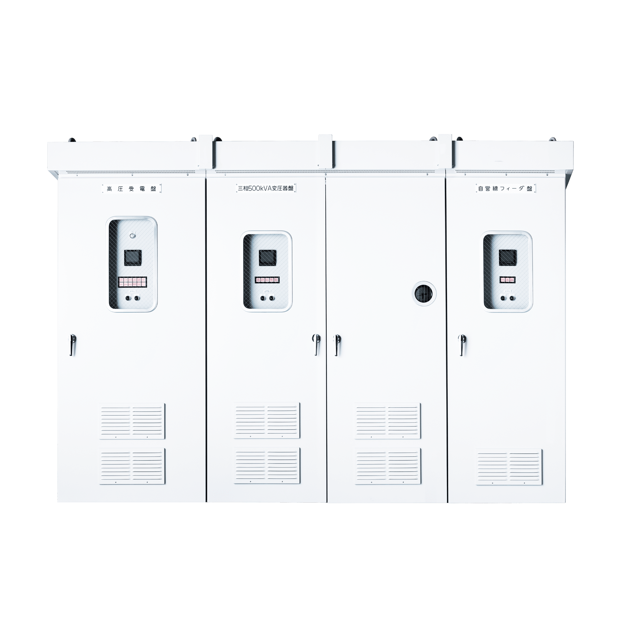
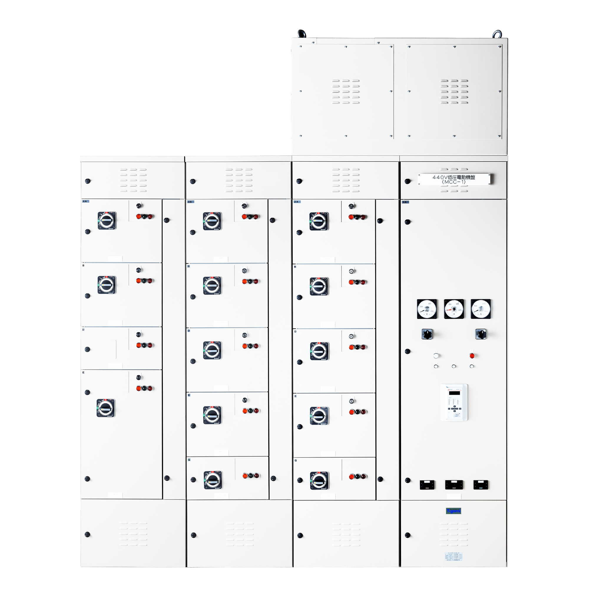
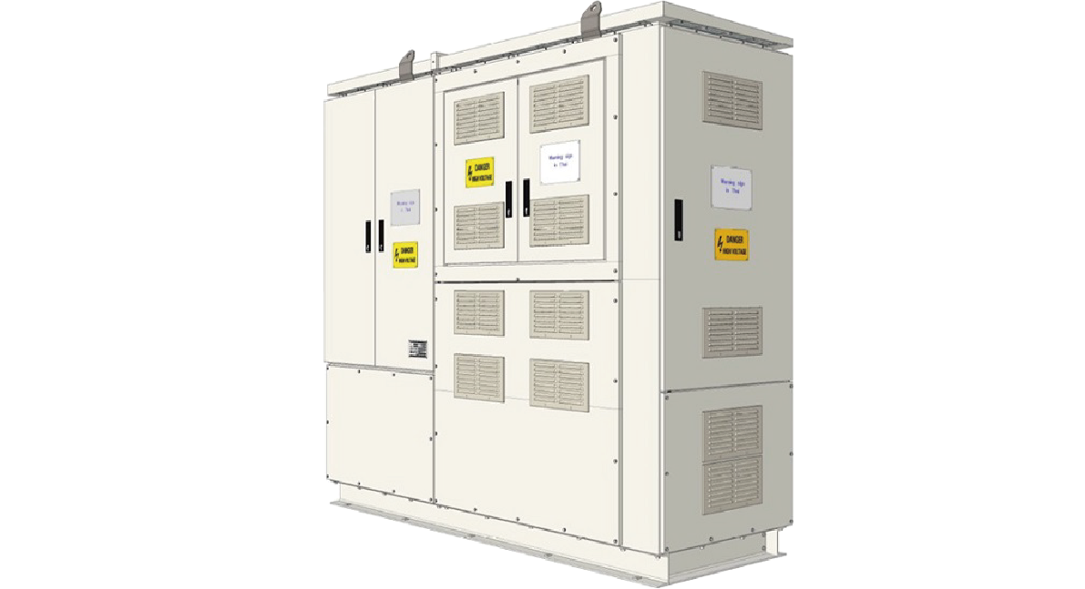
We offer an extensive lineup of different distribution boards, including high-voltage distribution boards. Flexible custom designs are possible by combining those functions required to meet customer needs.
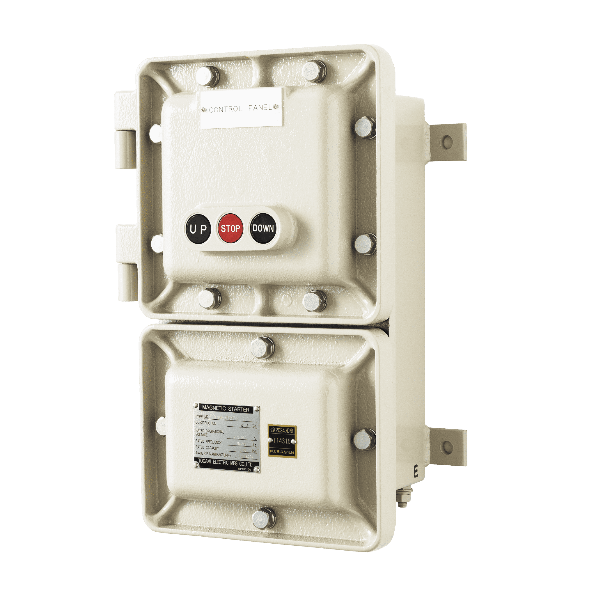
We offer a lineup of explosion-proof control equipment for use in explosion-proof areas, corrosion-resistant control equipment ideal for use in environments where corrosive gases are present.
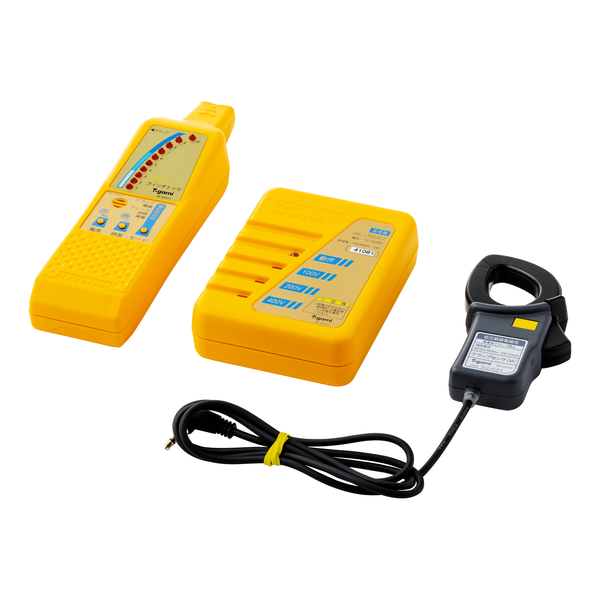
This is ideal for checking lines following faults or during maintenance before electrical equipment expansion or modification work. It allows live power lines to be checked by a single operator.
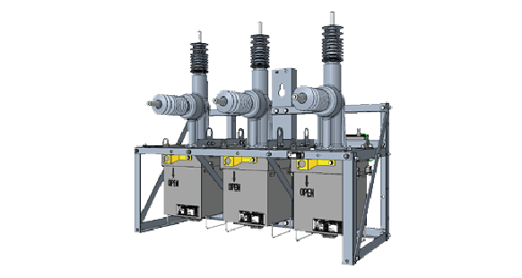
Togami Electric Mfg. Co., Ltd. designs, manufactures, and supplies Automatic Circuit Reclosers (Fault Clear) for power distribution lines.
We manufacture Ring Main Units (RMU) to connect, control, and protect different sections of a ring network.

『Make the society,
the Earth,
and the future prosperous!』

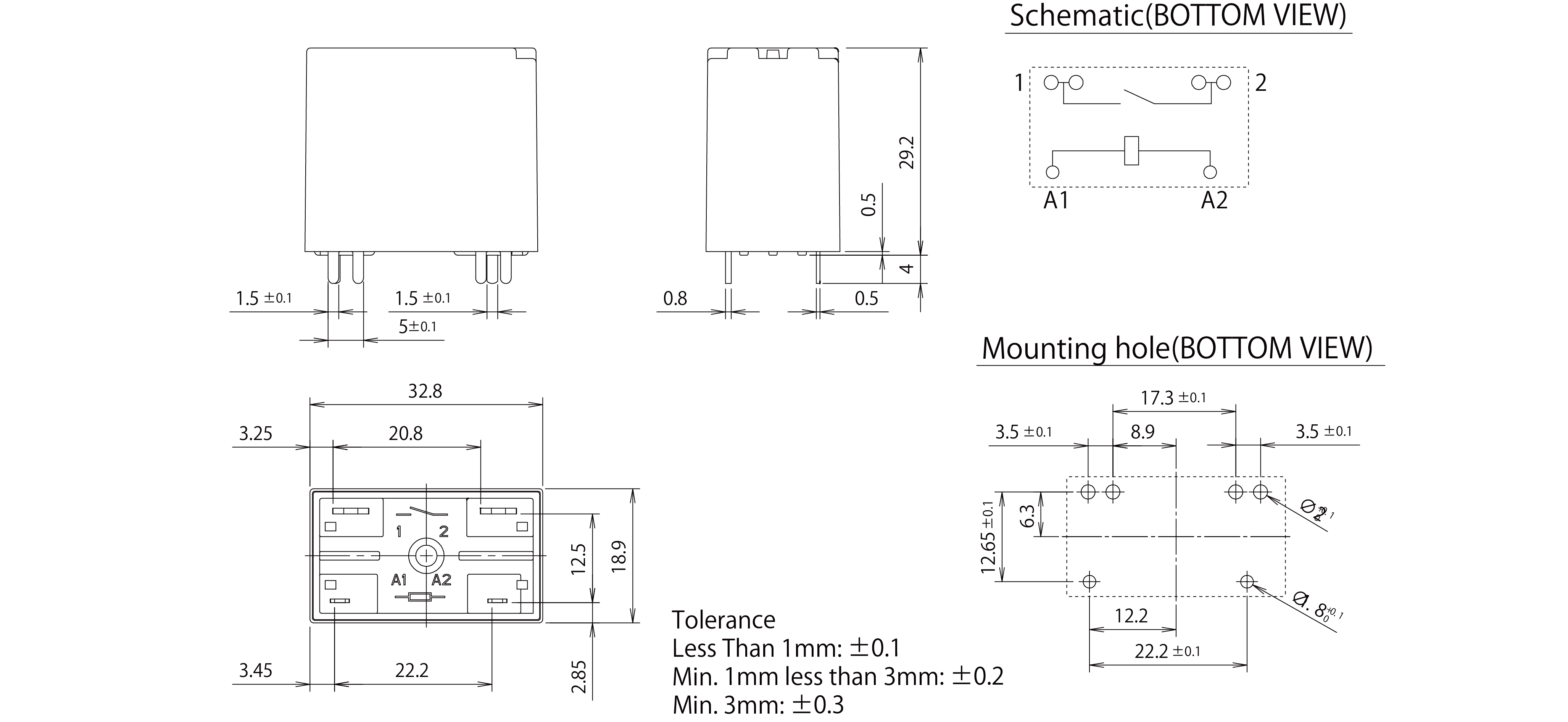
BRS-451LA
This relay is ideal for inrush current prevention in inverter power circuits. It is compact and has a high capacity. It increases the design flexibility of printed circuit boards, allowing for use in special atmospheres and is dustproof.

▼Contact rating for safety standard


| Model number | BRS-451LA | ||
|---|---|---|---|
| Contact configuration | 1a(NO) | ||
| Contact resistance(Initial) | Max. 100 mΩ(6 VDC,1 A, Voltage drop method) | ||
| Contact material | Silver alloy | ||
| Rated operating voltage | 480 VAC | ||
| Limiting continuous current | 45 A | ||
| Contact rating (Resistive load) |
250 VAC | 480 VAC | |
| 45 A Make/ 10 A break | 25 A Make/ 5 A break | ||
| Rated breaking capacity(50 operations) | 45 A(250 VAC) | ||
| Min. switching load | 100 mA,5 VDC | ||
| Electrical endurance | 10×103operations(Resistive load) | ||
| Mechanical endurance | 3×10⁶operations(No load) | ||
| Frequency of opening and closure | No load | 1,800 operations/ hour | |
| Resistive load | 120 operations/ hour | ||
| Operate voltage※1 | Max. 95% of the rated coil voltage | ||
| Release voltage | Min. 10% of the rated coil voltage | ||
| Limiting voltage | 110% of the rated coil voltage | ||
| Operation time | Max. 20 ms | ||
| Release time | Max. 10 ms | ||
| Insulation resistance(Initial) | Min. 1,000 MΩ | ||
| Dielectric strength(Initial) | Between open contacts:1,700 VAC for 1 minute | ||
| Between coil and contact:4,500 VAC for 1 minute | |||
| Rated impulse withstand voltage (Initial) |
Between open contacts:2,500 V(1.2×50 μs) | ||
| Between coil and contact:6,000 V(1.2×50 μs) | |||
| Protection | RT Ⅲ Wash tight relay(Plastic sealed) | ||
| Insulation characteristics (IEC 61810-1) |
Insulation distance:Clearance/ Creepage distance 5.5 mm/ 8.0 mm Type of disconnection:Micro disconnection Over voltage category:Ⅲ Materials group:Ⅲa Rated insulation voltage:500 V Rated insulation voltage:250 V Between coil and contact:Basic insulation Between coil and contact:Reinforced insulation Pollution degree:2 Pollution degree:3 |
||
| Shock resistance | Malfunction | Peak acceleration: 100 m/s2 Duration time: 11 ms | |
| Destruction | Peak acceleration: 1,000 m/s2 Duration time: 6 ms | ||
| Vibration resistance | Malfunction | Frequency range: 10 to 50 to 10 Hz Double amplitude: 1.5 mm |
|
| Destruction | |||
| Environmental conditions | Avoid icing and condensation. If left or used for a long period of time in a sulfur gas or organic gas atmosphere, the contact surface may corrode and contact resistance may increase. Do not use products containing silicon near relays. The permeability of the plastic allows silicone gas to penetrate inside the relay. Silicon oxide may form on the contact surface and cause contact failure. |
||
| Ambient temperature | -40 ℃ to 85 ℃ | ||
| Storage temperature | |||
| Ambient temperature and ambient humidity range Storage temperature and storage humidity range |
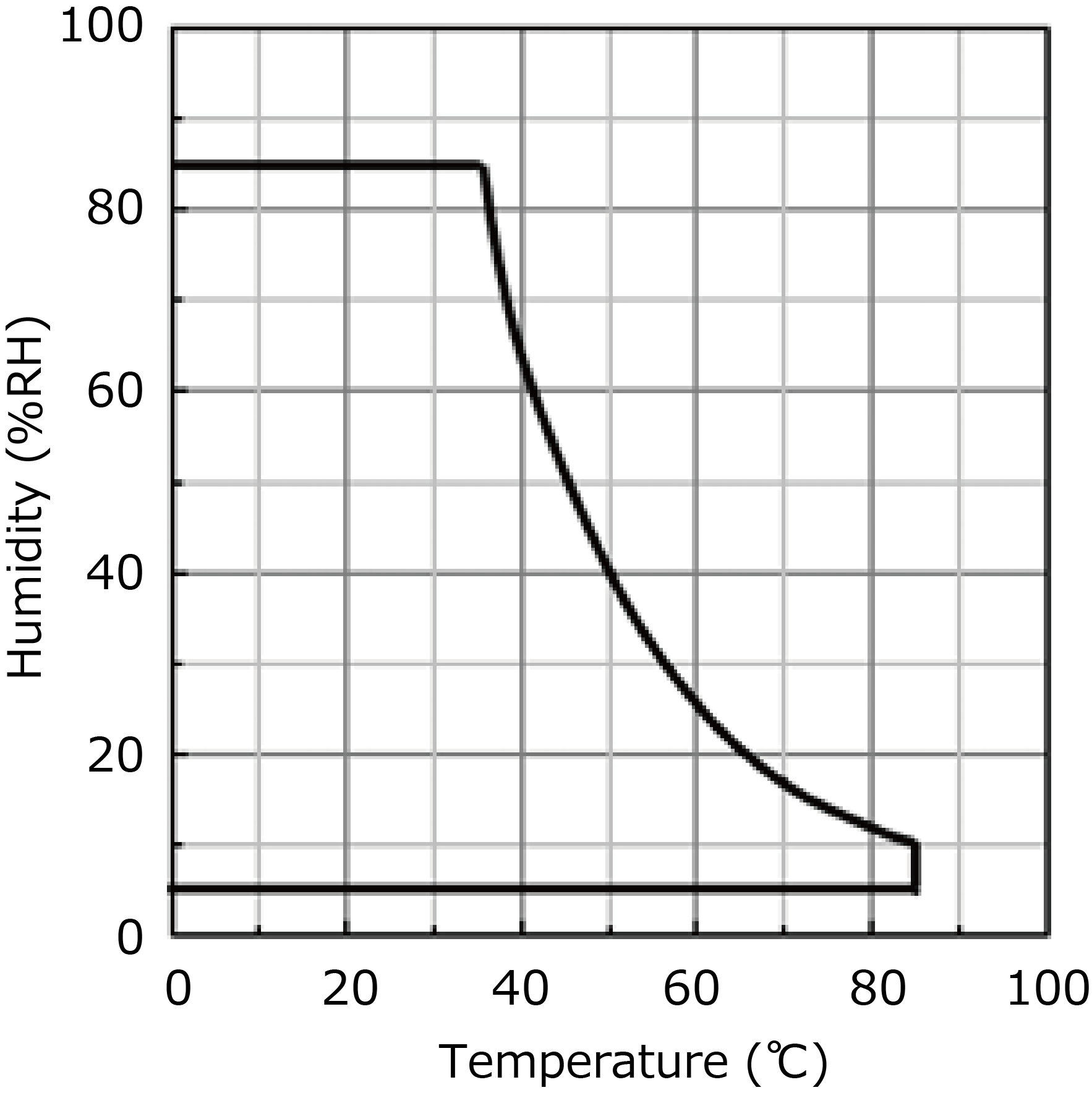 |
||
| Altitude | Max. 2,000 m | ||
| Solder heat resistance | Flow soldering Solder temperature 260±3 ℃ Solder dipping 5±0.5 s | ||
| Hand soldering Soldering iron temperature Max. 350 ℃ Solder dipping Max. 3 s | |||
| Mounting direction | No restriction | ||
| Weight | Approx. 35 g | ||
| Packing | Inner carton | 100 pcs. | |
| Shipping unit | 500 pcs. | ||
| Rated voltage | 6 VDC | 12 VDC | 24 VDC |
|---|---|---|---|
| Rated current | 150 mA | 75 mA | 46 mA |
| Rated power consumption | 0.9 W | 0.9 W | 1.1 W |
| Coil resistance ※±10% | 40 Ω | 160 Ω | 525 Ω |

| Rating | Electrical life | Operating temperature | |
|---|---|---|---|
| UL | 45 A Make/ 10 A Break, 277 VAC(Resistive load) 25 A Make/ 5 A Break, 480 VAC(Resistive load) 10 A 277 VAC(Resistive load) 5 A 480 VAC(Resistive load) |
10×103operations | at 85 ℃ |
| TUV | 45 A Make/ 10 A Break, 250 VAC(Resistive load) 25 A Make/ 5 A Break, 480 VAC(Resistive load) |
||
| CQC | 45 A Make/ 10 A Break, 250 VAC(Resistive load) 25 A Make/ 5 A Break, 480 VAC(Resistive load) |