GZR
Togami Electric Mfg. manufacturers standard electromagnetic contactor/starters, economical electromagnetic contactor/starters, DC-operated electromagnetic contactor/starters, and other types of electromagnetic contactor/starters.
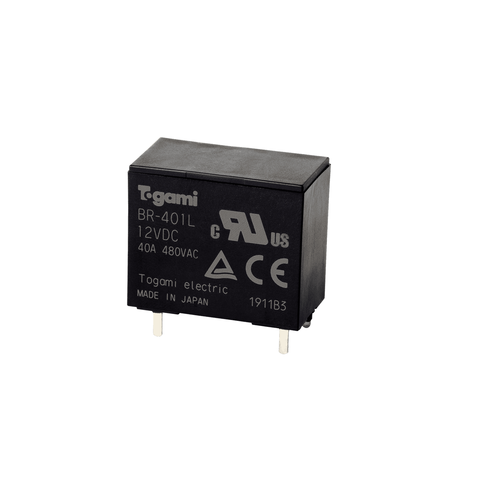
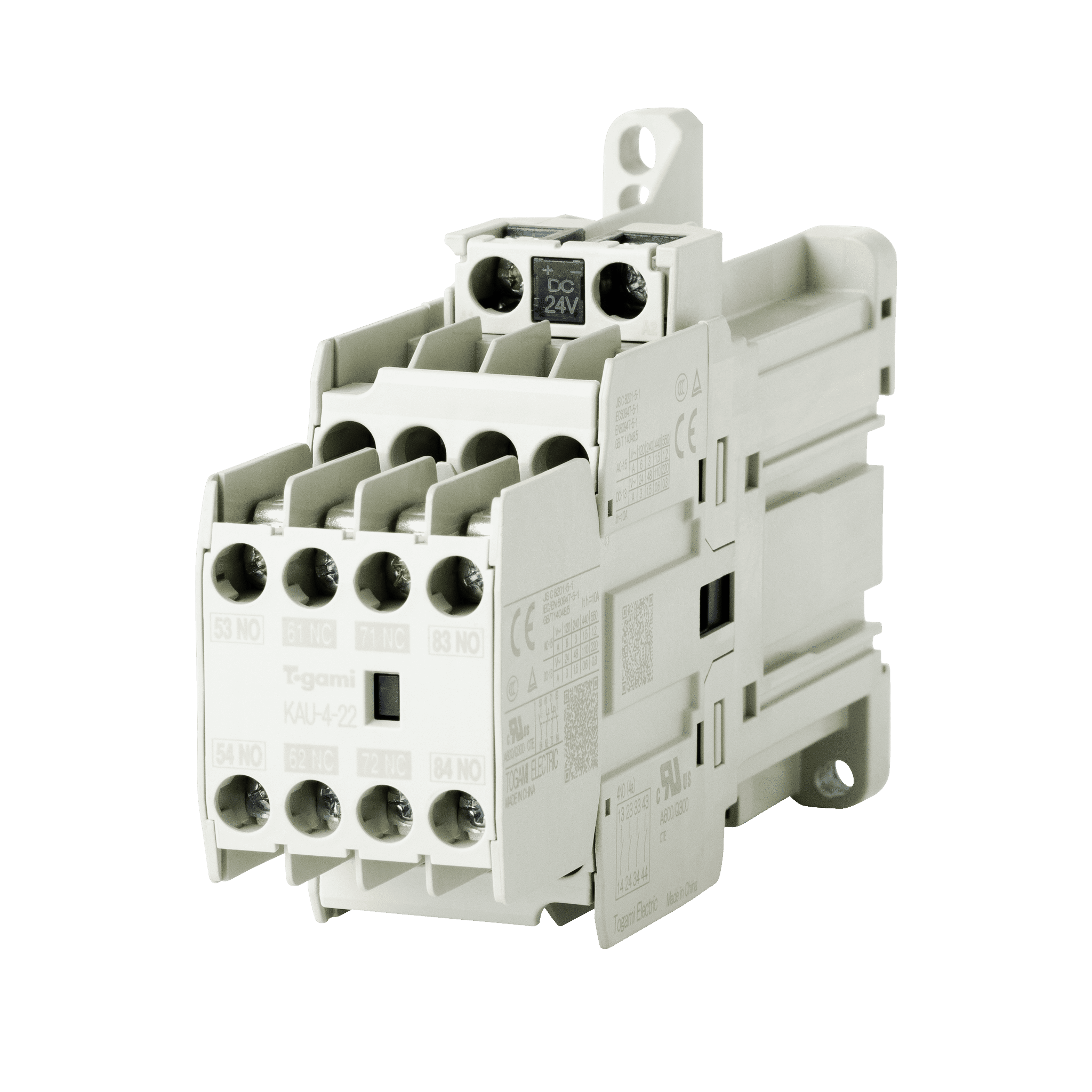
Our extensive lineup includes PCB relays used for inrush current prevention circuits and pre-charge circuits.
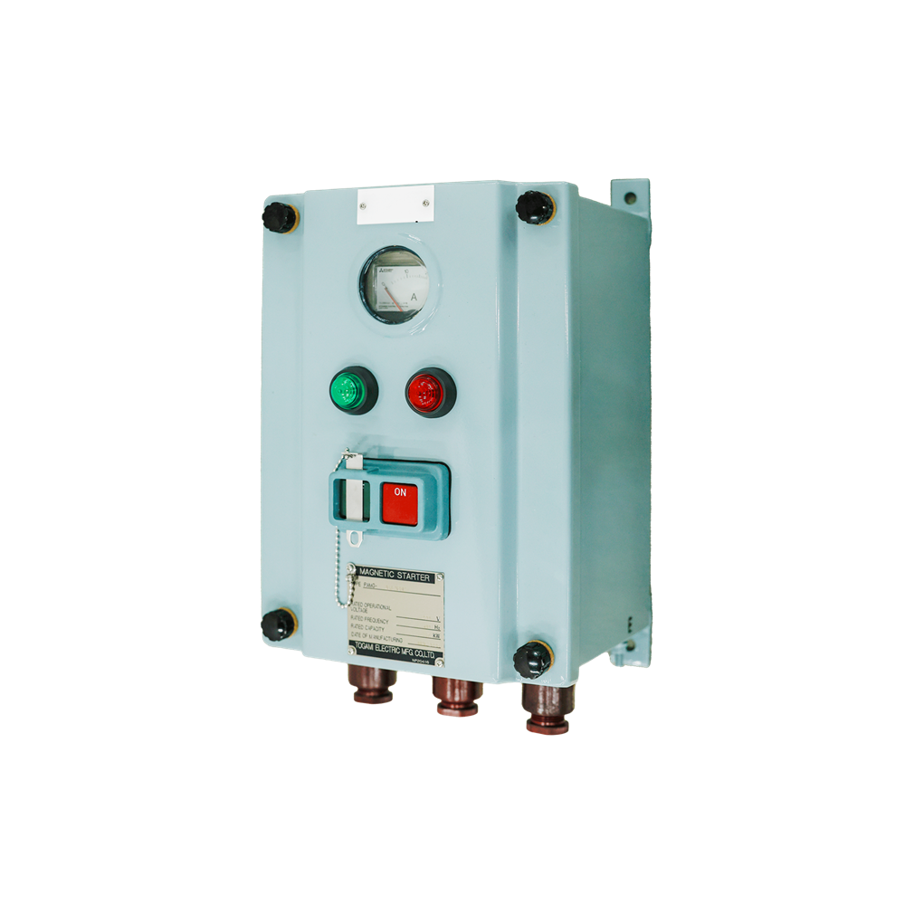
These are units for controlling the switching of equipment, including motors and pumps. They feature a compact design for cost-effectiveness and ease of use, allowing flexible custom designs combining the functions required to meet customer needs.
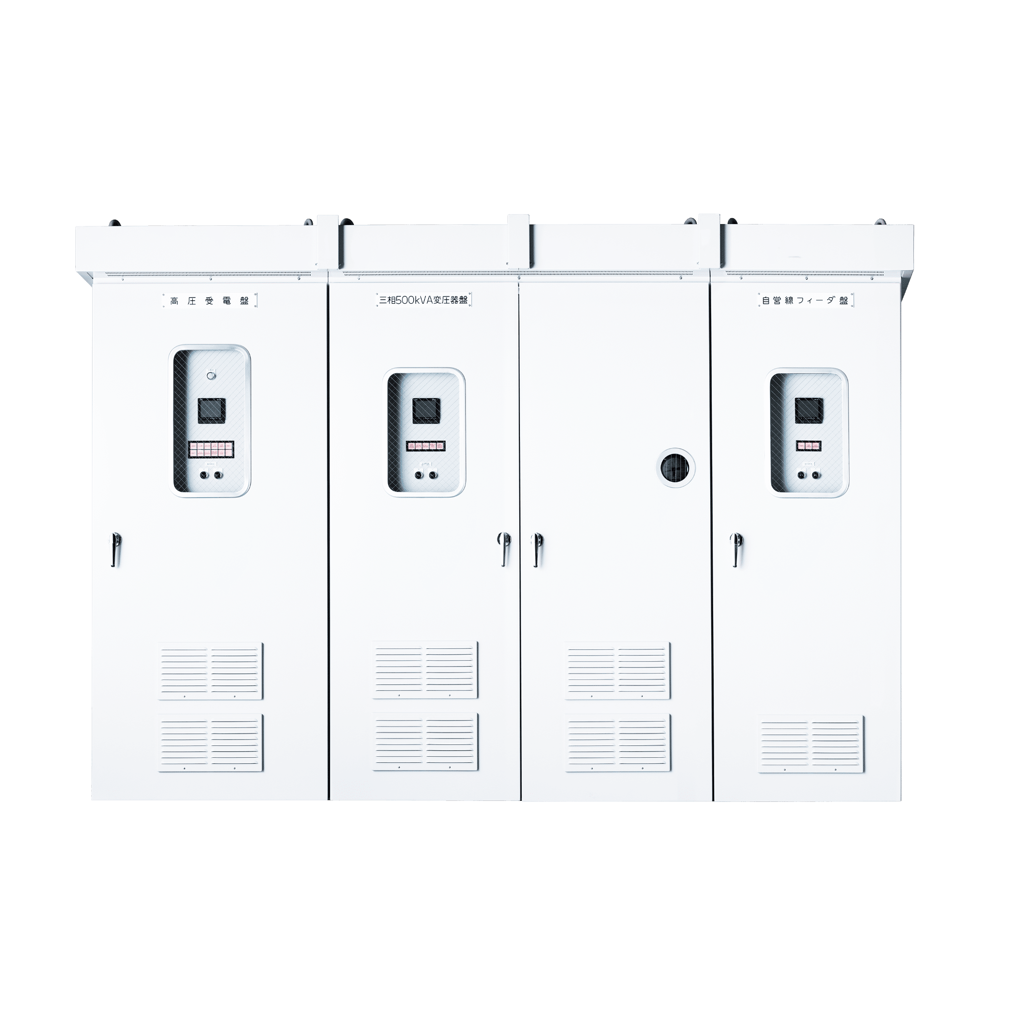
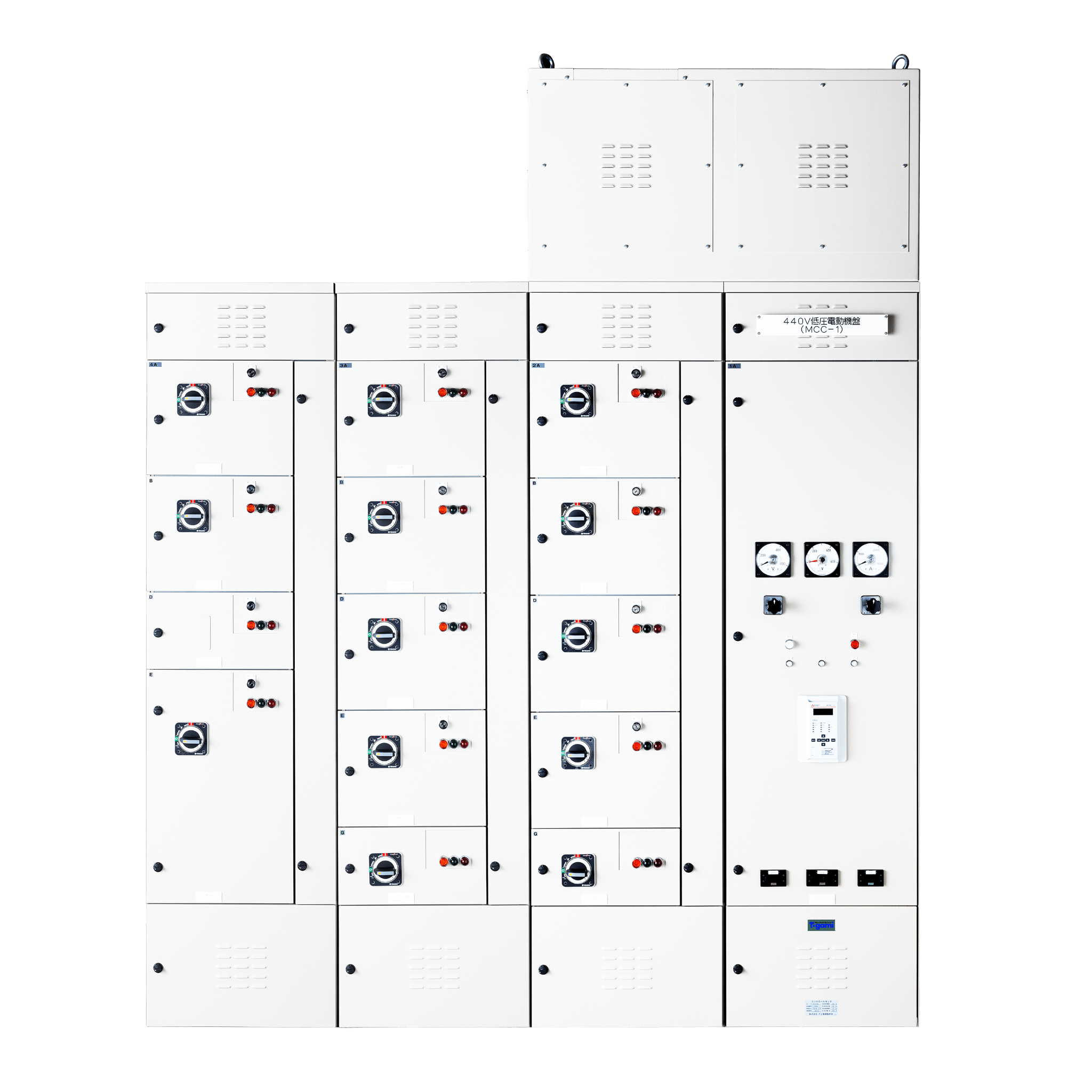
We offer an extensive lineup of different distribution boards, including high-voltage distribution boards. Flexible custom designs are possible by combining those functions required to meet customer needs.
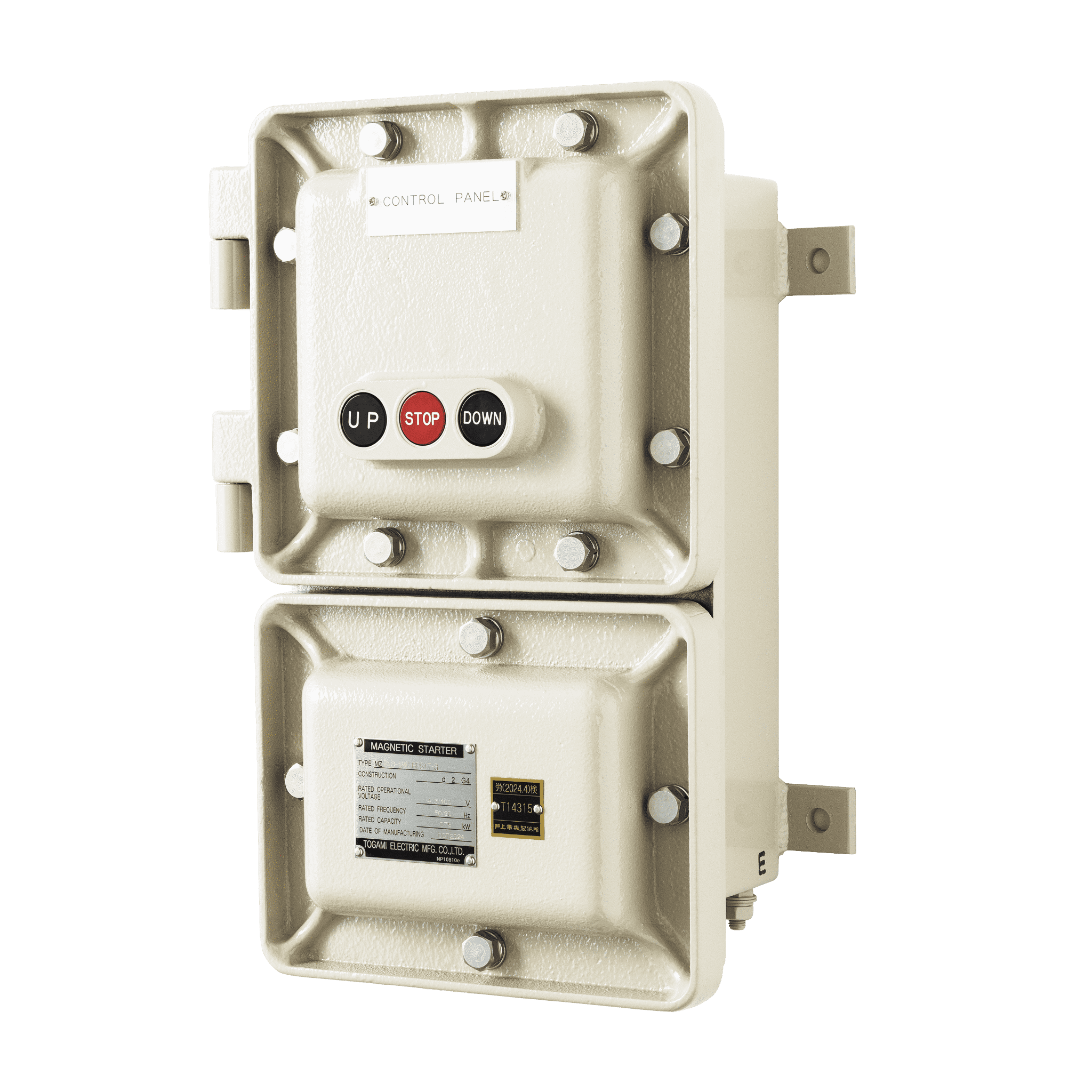
We offer a lineup of explosion-proof control equipment for use in explosion-proof areas, corrosion-resistant control equipment ideal for use in environments where corrosive gases are present.

This is ideal for checking lines following faults or during maintenance before electrical equipment expansion or modification work. It allows live power lines to be checked by a single operator.
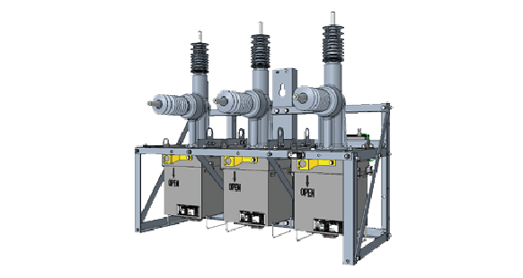
Togami Electric Mfg. Co., Ltd. designs, manufactures, and supplies Automatic Circuit Reclosers (Fault Clear) for power distribution lines.
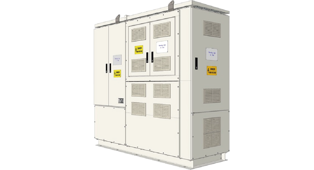
We manufacture Ring Main Units (RMU) to connect, control, and protect different sections of a ring network.

『Make the society,
the Earth,
and the future prosperous!』

GZR
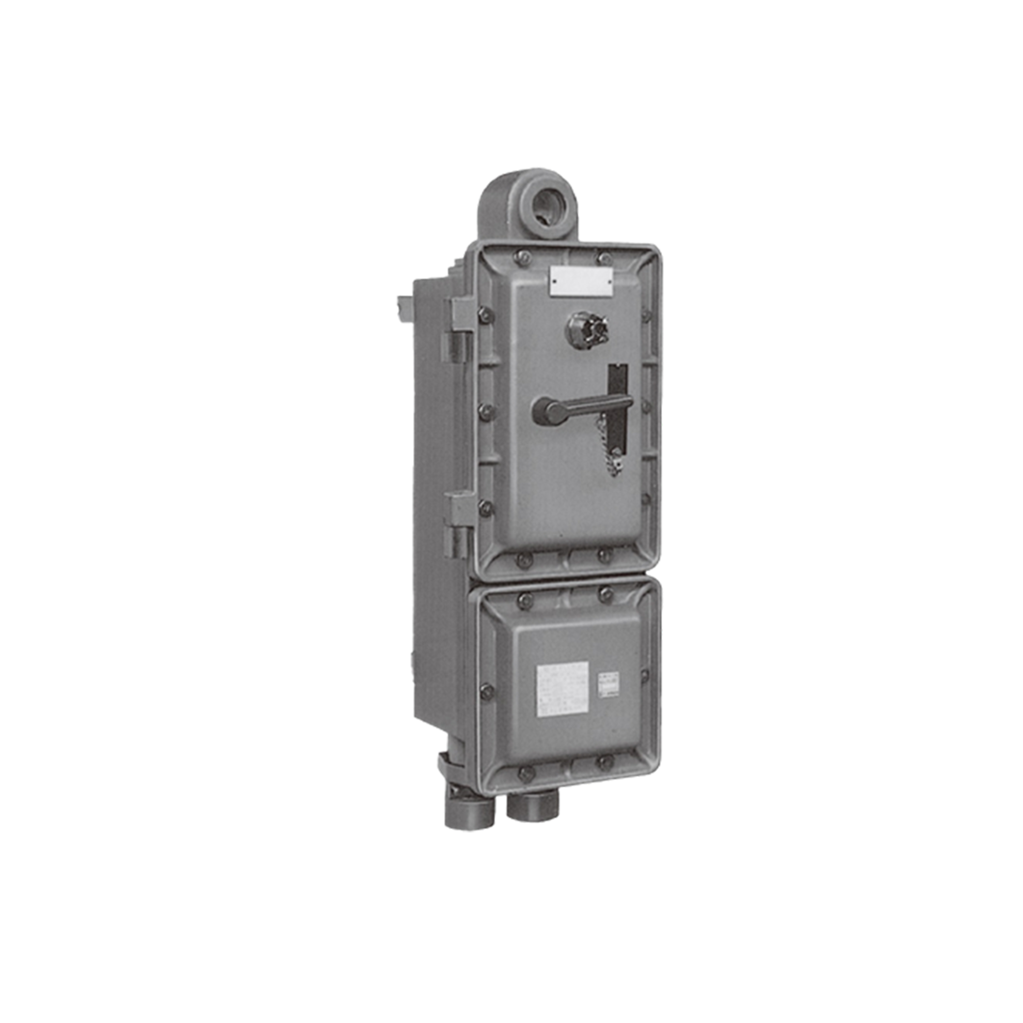
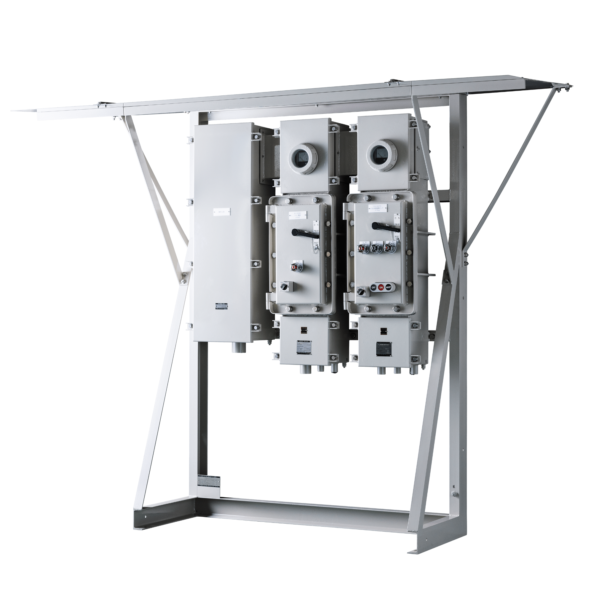
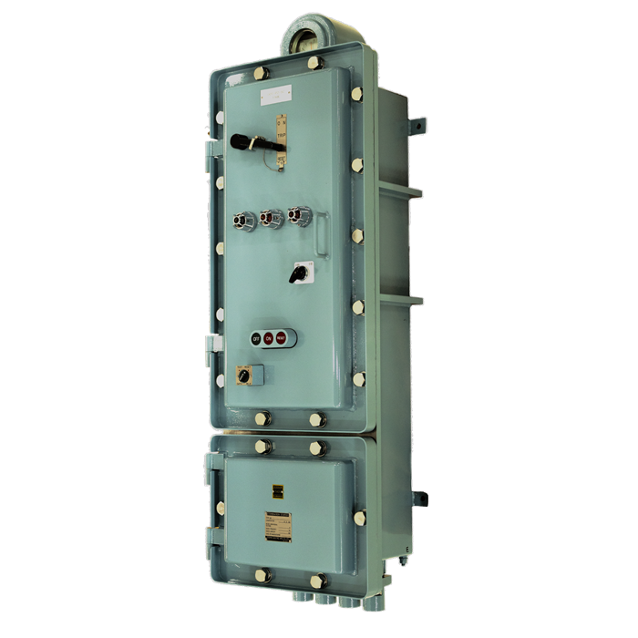
Explosion-proof combination starters with an explosion protection rating of d2G4※ (or de2G4※ for multi-unit types).
※ Electrical Equipment Explosion-Proof Design Standard (Japan)
| Type | Case model | Hazardous location | Explosion-proof construction |
|---|---|---|---|
| GZB | Upper and lower terminal boxes | Applicable in hazardous locations class 1 and 2 | d2G4 |
| GZR | Lower terminal box | Applicable in hazardous locations class 1 and 2 | d2G4 |
| GZL | Multi-unit type | Applicable in hazardous locations class 2 | de2G4 |
| Type | M.C.C.B | Magnetic switch MCS:star MCD:delta |
Maximum applicable load(kW) | Standard hub size(PF) | |||||||
|---|---|---|---|---|---|---|---|---|---|---|---|
| 200-220 V | 380-440 V | Power | Load | Control | |||||||
| Non-reversing | GZL | GZR | GZB | 1-A052 | 50 | PAK-26AF | 5.5 | 11 | 1 | 1 | 3/4 |
| 1-A053 | PAK-35AF | 7.5 | 15 | 1 | 1 | 3/4 | |||||
| 2-A052 | PAK-26AF | 5.5 | 11 | 1 | 1 | 3/4 | |||||
| 2-A053 | PAK-35AF | 7.5 | 15 | 1 | 1 | 3/4 | |||||
| 2-A055 | PAK-50AF | 11 | 22 | 1 1/4 | 1 1/4 | 3/4 | |||||
| 3-A108 | 100 | PAK-80AF | 19 | 37 | 1 1/4 | 1 1/4 | 3/4 | ||||
| 3-A110 | PAK-100AF | 22 | 45 | 1 1/2 | 1 1/2 | 3/4 | |||||
| 4-212 | 225 | PAK-125AF | 30 | 55 | 1 1/2 | 1 1/2 | 3/4 | ||||
| 4-215 | PAK-150AF | 40 | 75 | 2 | 2 | 3/4 | |||||
| 5-225 | PAK-220AF | 50 | 90 | 2 1/2 | 2 1/2 | 3/4 | |||||
| 5-425 | 400 | PAK-220AF | 55 | 90 | 2 1/2 | 2 1/2 | 3/4 | ||||
| 5-430 | PAK-300AF | 75 | 150 | 2 1/2 | 2 1/2 | 3/4 | |||||
| Reversing | GZL | GZR | GZB | 2-A052R | 50 | RSK-26AF | 5.5 | 11 | 1 | 1 | 3/4 |
| 2-A053R | RSK-35AF | 7.5 | 15 | 1 | 1 | 3/4 | |||||
| 3-A052R | RSK-26AF | 5.5 | 11 | 1 | 1 | 3/4 | |||||
| 3-A053R | RSK-35AF | 7.5 | 15 | 1 | 1 | 3/4 | |||||
| 4-055R | RSK-50AF | 11 | 22 | 1 1/4 | 1 1/4 | 3/4 | |||||
| 4-108R | 100 | RSK-80AF | 19 | 37 | 1 1/4 | 1 1/4 | 3/4 | ||||
| 4-110R | RSK-100AF | 22 | 37 | 1 1/2 | 1 1/2 | 3/4 | |||||
| 5-112R | RSK-125AF | - | 45 | 1 1/2 | 1 1/2 | 3/4 | |||||
| 5-215R | 225 | RSK-150AF | 40 | 75 | 2 | 2 | 3/4 | ||||
| Star-delta | GZL | GZR | GZB | 2-A053Y | 50 | MCS:PAK-26AF MCD:PAK-26AF |
7.5 | 11 | 1 | 1×2 | 3/4 |
| 2-A055Y | MCS:PAK-26AF MCD:PAK-35AF |
11 | 19 | 1 1/4 | 1 1/4×2 | 3/4 | |||||
| 3-A053Y | MCS:PAK-26AF MCD:PAK-26AF |
7.5 | 11 | 1 | 1×2 | 3/4 | |||||
| 3-A055Y | MCS:PAK-26AF MCD:PAK-35AF |
11 | 19 | 1 1/4 | 1 1/4×2 | 3/4 | |||||
| 3-A108Y | 100 | MCS:PAK-35AF MCD:PAK-50AF |
19 | 26 | 1 1/4 | 1 1/4×2 | 3/4 | ||||
| 4-110Y | MCS:PAK-50AF MCD:PAK-65AF |
22 | 37 | 1 1/2 | 1 1/2×2 | 3/4 | |||||
| 5-215Y | 225 | MCS:PAK-65AF MCD:PAK-100AF |
40 | 55 | 2 | 2×2 | 3/4 | ||||
| 5-225Y | MCS:PAK-100AF MCD:PAK-150AF |
50 | 90 | 2 1/2 | 2 1/2×2 | 3/4 | |||||
<Common specifications>
1.Material・・・The molded case and cover: Steel type
2.Outside breaker with handle
3.The molded case circuit breaker can be controlled by means of an external operating handle and handle can be locked at the OFF-position by the use of locking pin.
4.The service entrance is flameproof threaded joint steel conduit leading type.
5.The equipment name plate is provided. Name indication is made on an acryl plate in black letters on a white field.
6.Painting Color:
Internal and external surfaces of enclosures: Munsell No.7.5BG6/1.5
The molded case circuit breaker operating handle: Munsell No.N1.5
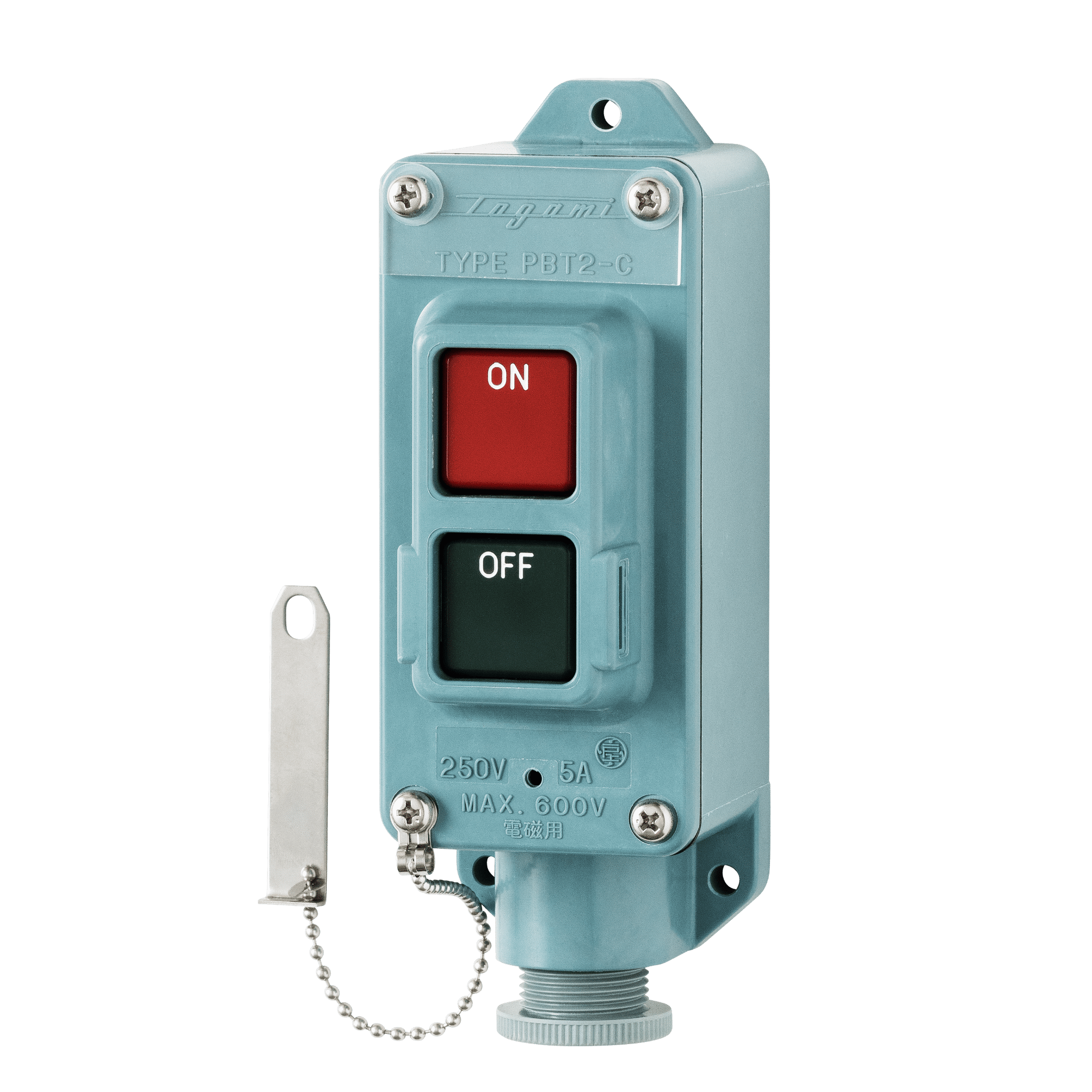
7.The operating push-buttons have indications in English on their surfaces. The color of ON push-button is red and OFF push-button is green.
8.The OFF push-button has a locking device.
9.The thermal overload relay is external manual-resetting type, equipped with a resetting push-button installed on the cover. The color of the resetting push-button is
red and it has indications in Japanese and English on its surface.
10.Remote and direct control: Please add supplementary specifications of code to 「B」.
| Type | Enclosure type No. | Dimension(mm) | Weight(kg) | |||||||
|---|---|---|---|---|---|---|---|---|---|---|
| A | B | C | D | E | F | G | P | |||
| GZB | 1 | 907 | 299 | 325 | 700 | 240 | 103 | - | M12 | 68 |
| 2 | 1033 | 355 | 330 | 700 | 280 | 153 | - | M16 | 105 | |
| 3 | 1233 | 371 | 355 | 900 | 300 | 168 | - | M16 | 130 | |
| 4 | 1603 | 491 | 364 | 1200 | 380 | 203 | - | M20 | 230 | |
| 5 | 2025 | 571 | 367 | 1500 | 480 | 264 | - | M20 | 330 | |
| GZR | 1 | 695 | 299 | 324 | 500 | 240 | 64 | 101 | M12 | 50 |
| 2 | 791 | 355 | 330 | 500 | 280 | 117 | 97 | M16 | 75 | |
| 3 | 961 | 371 | 355 | 650 | 300 | 133 | 97 | M16 | 100 | |
| 4 | 1240 | 491 | 364 | 900 | 380 | 140 | 126 | M20 | 205 | |
| 5 | 1602 | 571 | 367 | 1100 | 480 | 264 | 126 | M20 | 280 | |
| GZL | 1 | 1053 | 299 | 362 | 650 | 240 | 358 | - | M12 | 63 |
| 2 | 1141 | 355 | 367 | 650 | 280 | 358 | - | M16 | 92 | |
| 3 | 1305 | 371 | 367 | 650 | 300 | 358 | - | M16 | 120 | |
| 4 | 1535 | 491 | 376 | 650 | 380 | 358 | - | M20 | 220 | |
| 5 | 1876 | 571 | 379 | 1100 | 480 | 358 | - | M20 | 300 | |
・Wiring, operation, maintenance, and inspections of these products must be performed by personnel with specialized knowledge and skills in the installation of explosion-proof electrical equipment and related regulations.
・For installations in hazardous locations, please check the applicable hazardous area classification. The hazardous areas in which products may be installed will vary depending on the specific model.
・Please note that specfications, dimensions, etc., are subject to change without prior notice.
Prior to installed of explosion-proof electrical equipments, careful study should be made on the following recommendations.
1. To prevent explosions or files caused by the electrical equipments, every effort should be made, as a prerequisite, to minimize possible danger of explosion at a location where they are to be installed.
2. The electrical equipments should be installed at a location with a minimum posibility of explosion. In case, however, they are unavoidably installed at a hazardous location where explosion is expected, it should be limited to a minimum extent.
3. The explosion-proof electrical equipments to be installed should be the products that have been proved to fully meet he requirements.
Study the sorts of inflammable gas or steam present at a location where the electrical equipments are to be installed in order to determine the explosion class and the firing degree. Then, determine the hazardous locations according to the degree of danger of the locations where the electrical equipments are to be installed. The explosion-proof electrical equipments may be selected on the basis of the determination of explosion class, firing degree and hazardous locations.
The danger class of explosive gas is determined by the firing degree and explosion class.
| Firing degree | Firing point |
|---|---|
| G1 G2 G3 G4 G5 |
over 450 ℃ over 300 ℃ up to 450 ℃ over 200 ℃ up to 300 ℃ over 135 ℃ up to 200 ℃ over 100 ℃ up to 135 ℃ |
| Explosion class | Minimum clearance which permits flame running at 25 mm. |
|---|---|
| 1 2 3 |
over 0.6 mm over 0.4 mm up to 0.6 mm up to 0.4 mm |
| G1 | G2 | G3 | G4 | G5 | |
|---|---|---|---|---|---|
| 1 | Ammonia Carbon monoxide Acetic acid Propane Methane |
Ethanole Amyl Acetate-iso 1-Buthanole Butane Acetic anhydride |
Gasoline Hexane |
Acetaldehyde Ethylether |
|
| 2 | Coal gas | Ethylene Ethylene oxide |
|||
| 3 | Water gas Hydrogen |
Acetylene |
The areas of possible danger or to be dangerous atmosphere are classfield into class 0, class 1 and class 2 depending upon the dangerous time and frequency of occurrence of danger.
Class 0・・・Where dangerous density of explosive gas continues or is held for a long time above the lower limit of an explosion.
Class 1・・・Where a dangerous atmosphere is expected to be present under normal state.
Class 2・・・Where a dangerous atmosphere is expected to be present under abnormal state.
The explosion-proof construction is designed to protect the equipment in use at a hazardous location and can be divided into many different types including pressure-resisting explosion-proof(d), oil-immersed explosion-proof(o), internal pressure-resisting explosion-proof(f), increased safety explosion-proof(e), substantial safety explosion-proof(i), special explosion-proof(s) and other varying types. Out of them, the following construction types are employed in the explosion-proof electrical equipment introduced in this paper.
※ Pressure-resisting explosion-proof type(d)
This is of a totally enclosed construction, and should an explosion take place inside the enclosure, the enclosure resists the resultant pressure eliminating a danger of igniting an explosive gas outside.
※ Increased safety explosion-proof type(e)
This is of the construction which is particularly provided with increased safety on its construction or temperature rise, in order to prevent sparking arcing and overheating on those parts which should not essentially generate them.