- Togami Electric's Strengths
-
Products
-
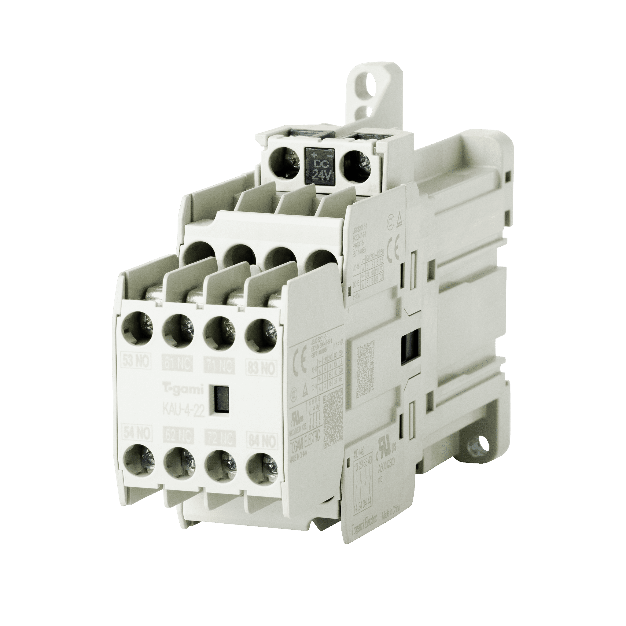
Magnetic Contactor / Starter
Togami Electric Mfg. manufacturers standard electromagnetic contactor/starters, economical electromagnetic contactor/starters, DC-operated electromagnetic contactor/starters, and other types of electromagnetic contactor/starters.
-
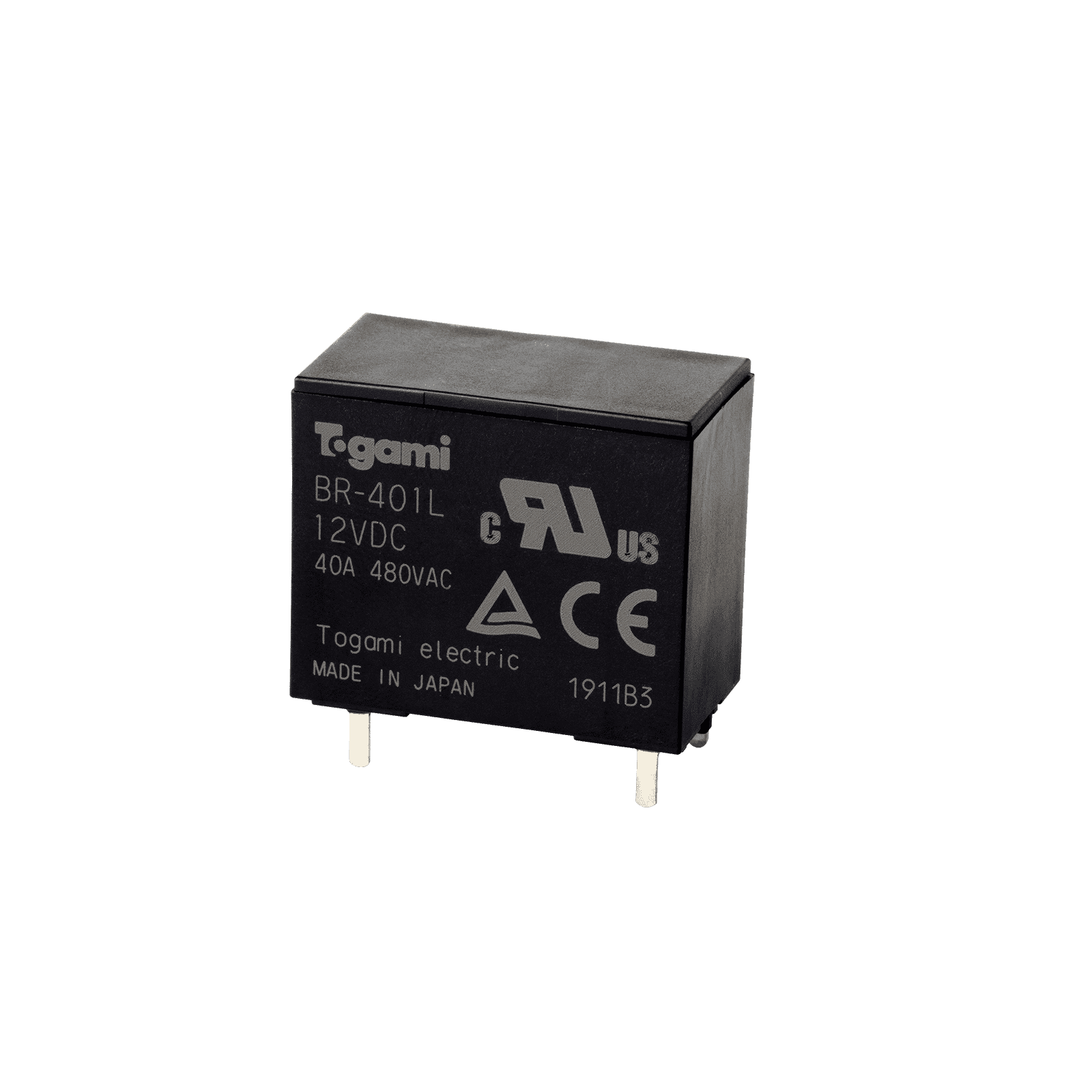
PCB Relay
Our extensive lineup includes PCB relays used for inrush current prevention circuits and pre-charge circuits.
-
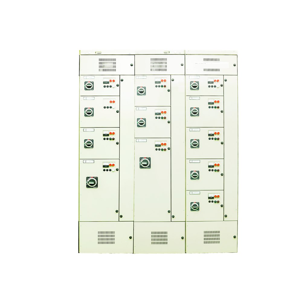
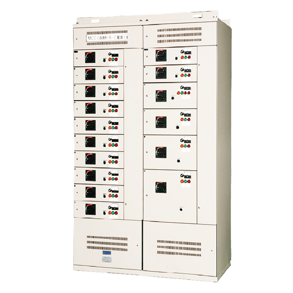
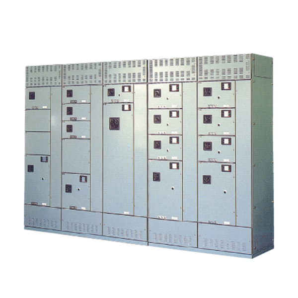
Motor Control Center
These are units for controlling the switching of equipment, including motors and pumps. They feature a compact design for cost-effectiveness and ease of use, allowing flexible custom designs combining the functions required to meet customer needs.
-
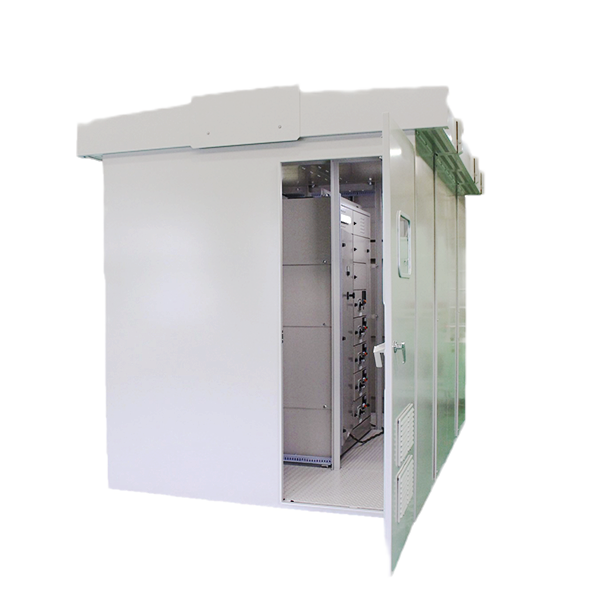
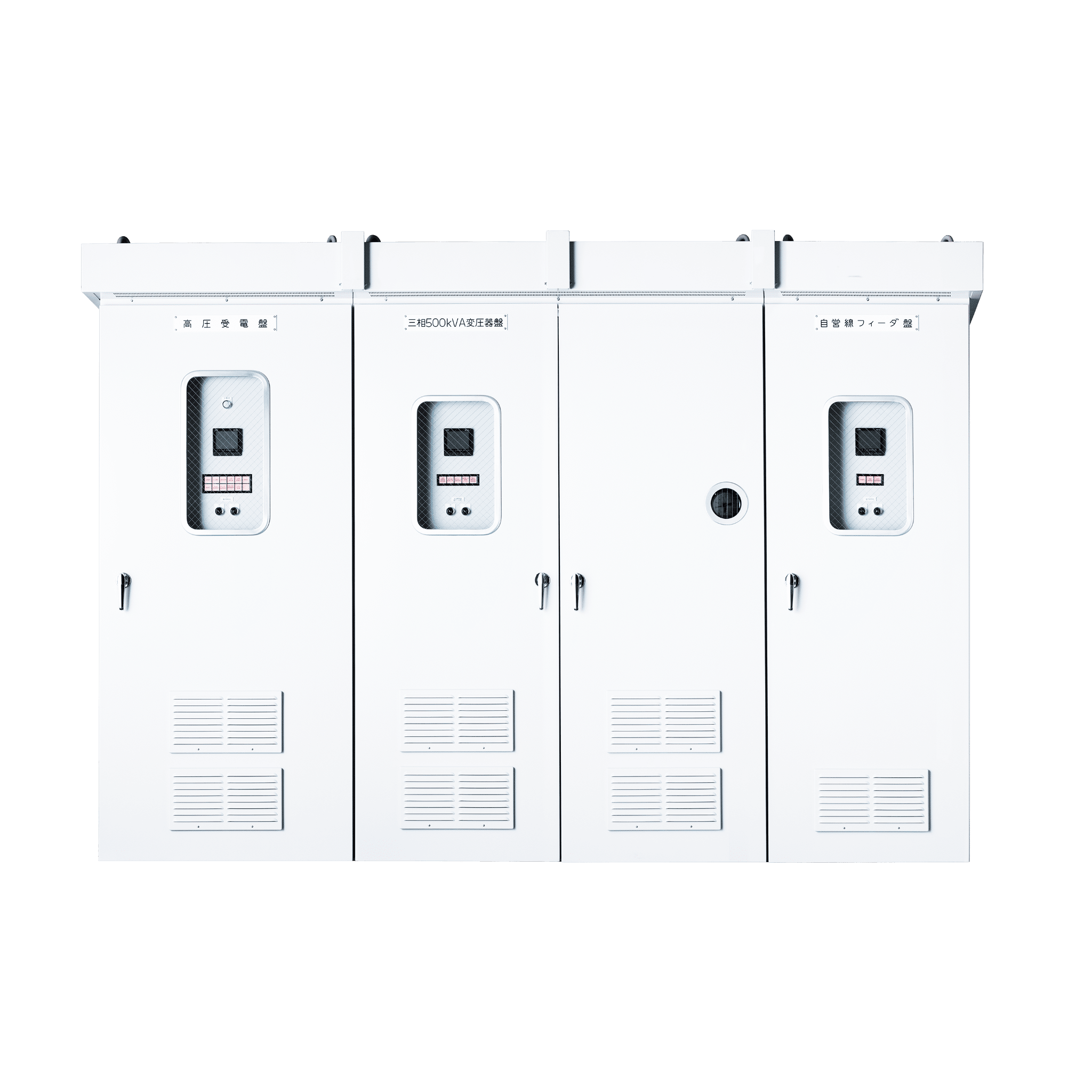
Switchboard
We offer an extensive lineup of different distribution boards, including high-voltage distribution boards. Flexible custom designs are possible by combining those functions required to meet customer needs.
-
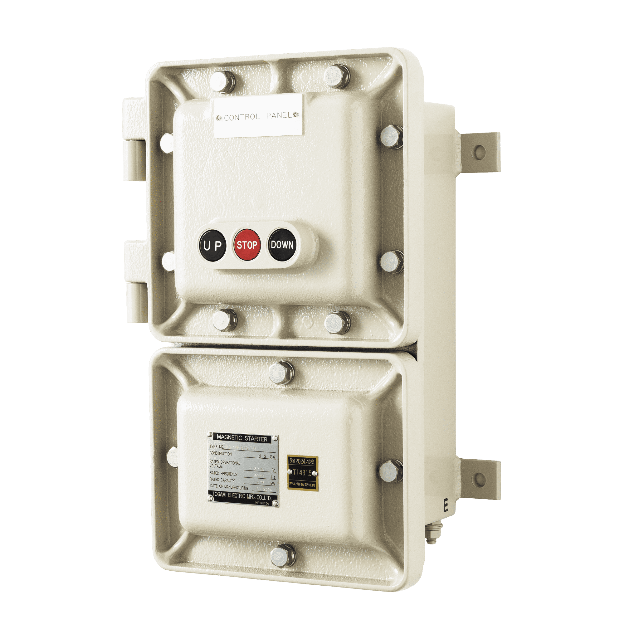
Explosion-Proof and Corrosion-Resistant Control Equipment
We offer a lineup of explosion-proof control equipment for use in explosion-proof areas, corrosion-resistant control equipment ideal for use in environments where corrosive gases are present.
-
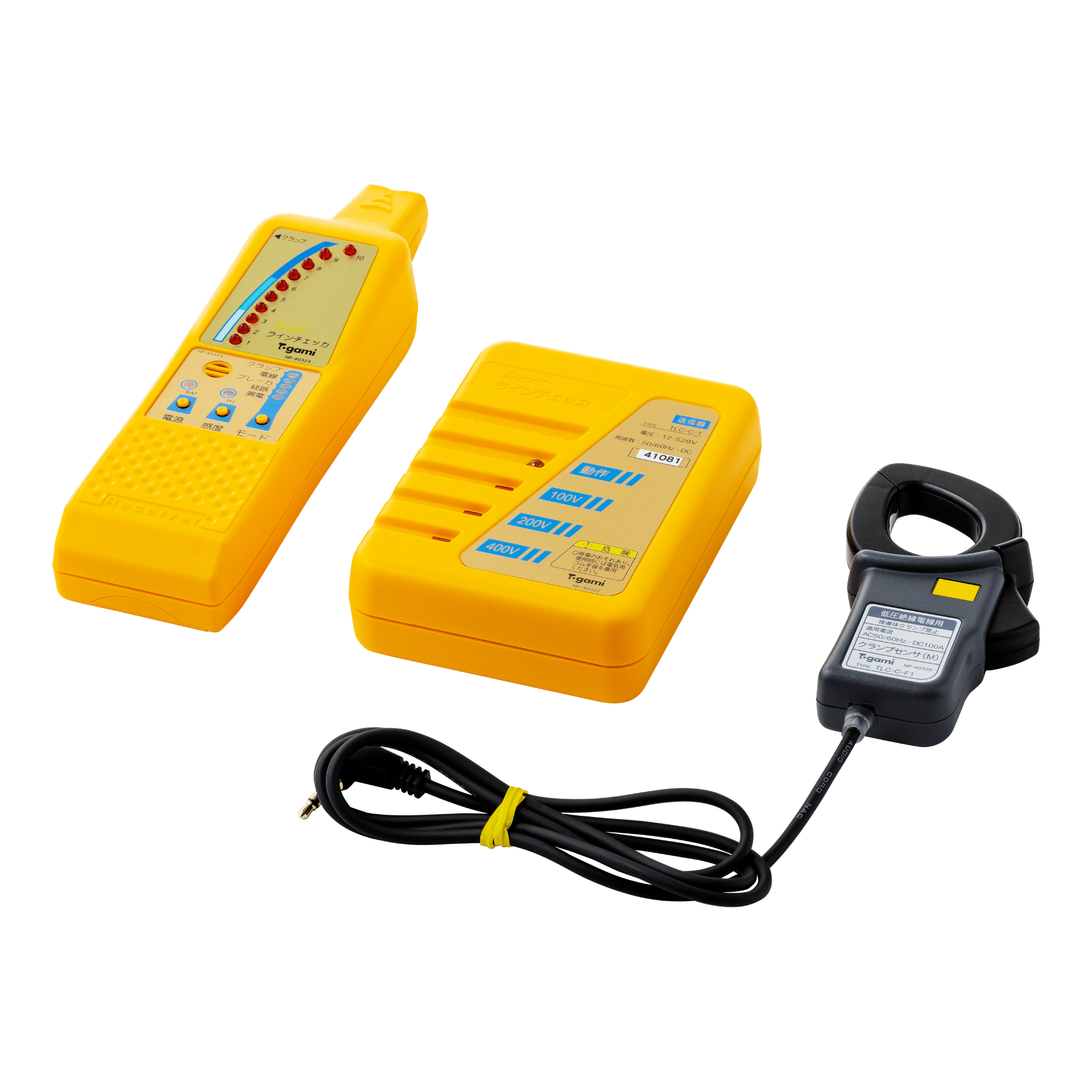
Super Line Checker
This is ideal for checking lines following faults or during maintenance before electrical equipment expansion or modification work. It allows live power lines to be checked by a single operator.
-
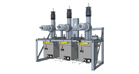
Recloser
Togami Electric Mfg. Co., Ltd. designs, manufactures, and supplies Automatic Circuit Reclosers (Fault Clear) for power distribution lines.
-
Ring Main Unit (RMU)
We manufacture Ring Main Units (RMU) to connect, control, and protect different sections of a ring network.

- Company
-
COMPANY
『Make the society,
the Earth,
and the future prosperous!』 -

- Sustainability
- TOP
- Products
- Motor Control Center
- NH-C Type Control Center
PRODUCTS
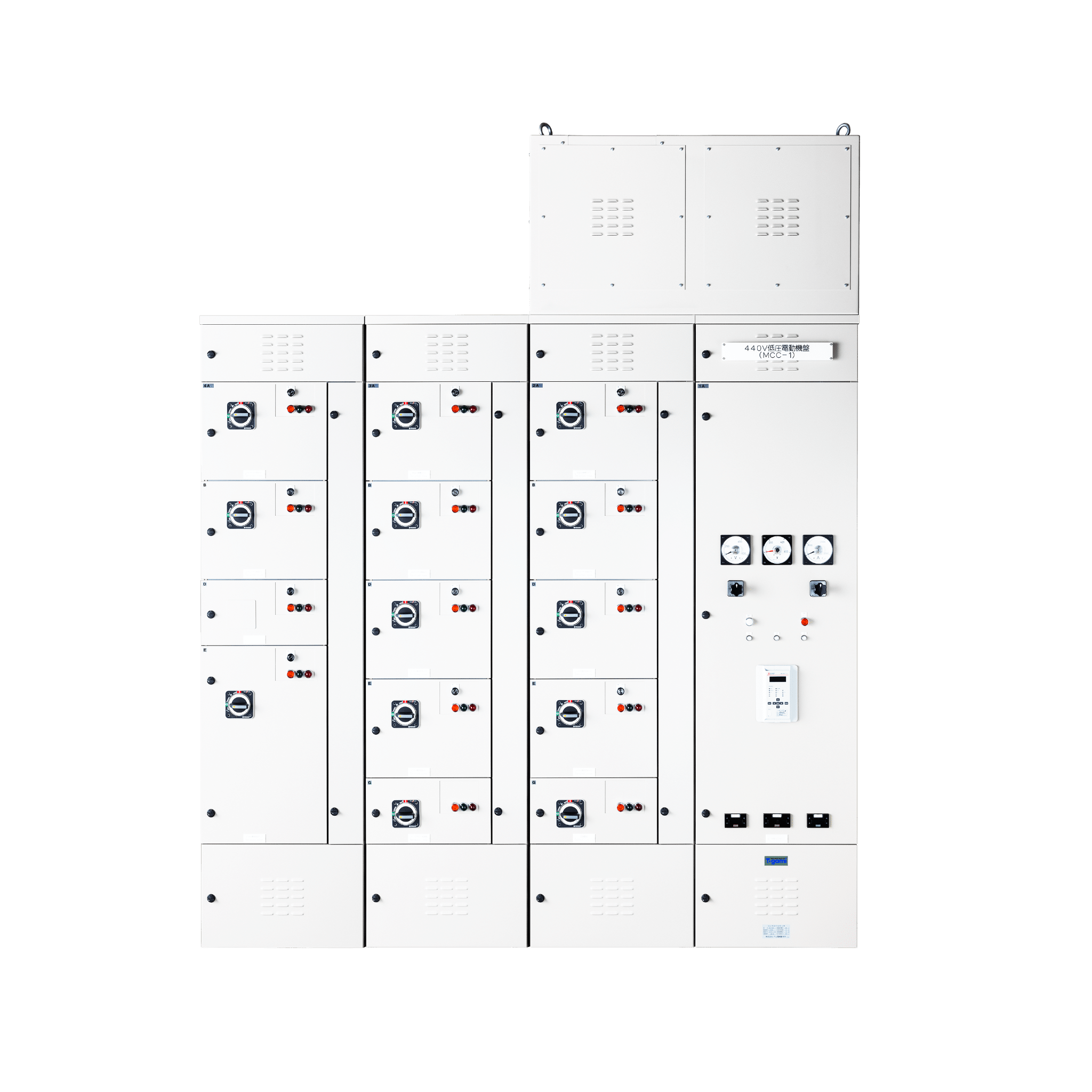
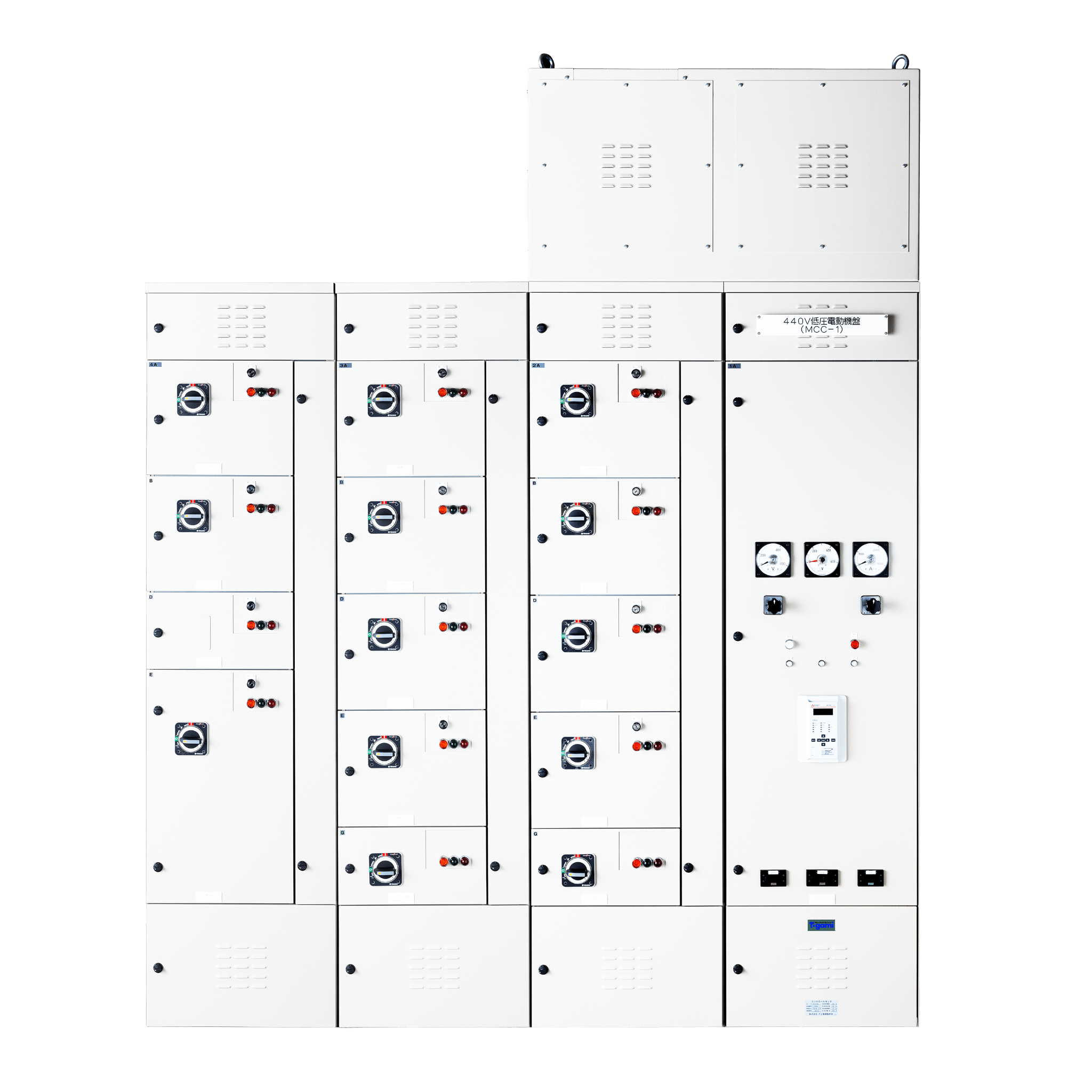
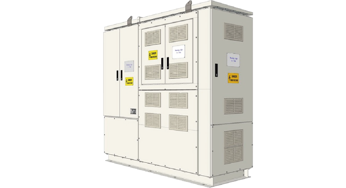
NH-C Type Control Center
NH-C control centers are designed for field use, with a focus on safety, ease of use, and ease of maintenance. Units can be stored with the door closed in all three positions(disconnecting, testing, and connecting).
Features
- Units can be stored with the door closed in all three positions(disconnecting, testing, and connecting).
- The main circuit contacts can be easily moved by operating lever. Automatic locking system is equipped with all three positions in order to prevent incomplete connection and disconnection faults.
- The units employ a mechanical interlocking mechanism which allows them to be inserted or withdrawn from the frame at the disconnecting position only.
- The protection rating between horizontal and vertical busbars is IP40.
- Easy connection and maintenance of the horizontal busbars are possible because of the isolated horizontal busbar connecting compartment.
- Unit replacement is possible without power interruption.
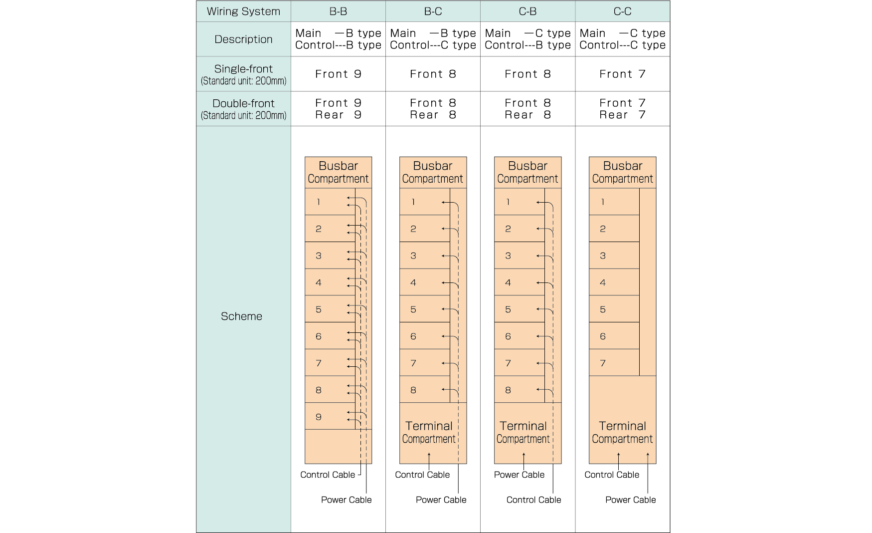
Specifications
Wiring types and number of units to insert
Operation with operating lever
【Example:Disconnecting position → Testing position → Connecting position】
Interlocking mechanism is employed so as not to insert and remove the operating lever at other than three positions.
※ This feature guarantees protection from incomplete connection and disconnection faults either at the supply or load side contacts.
Removing the operating lever will lock each position automatically, and doors can be closed.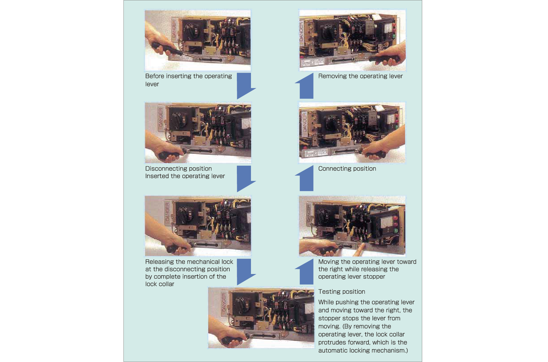
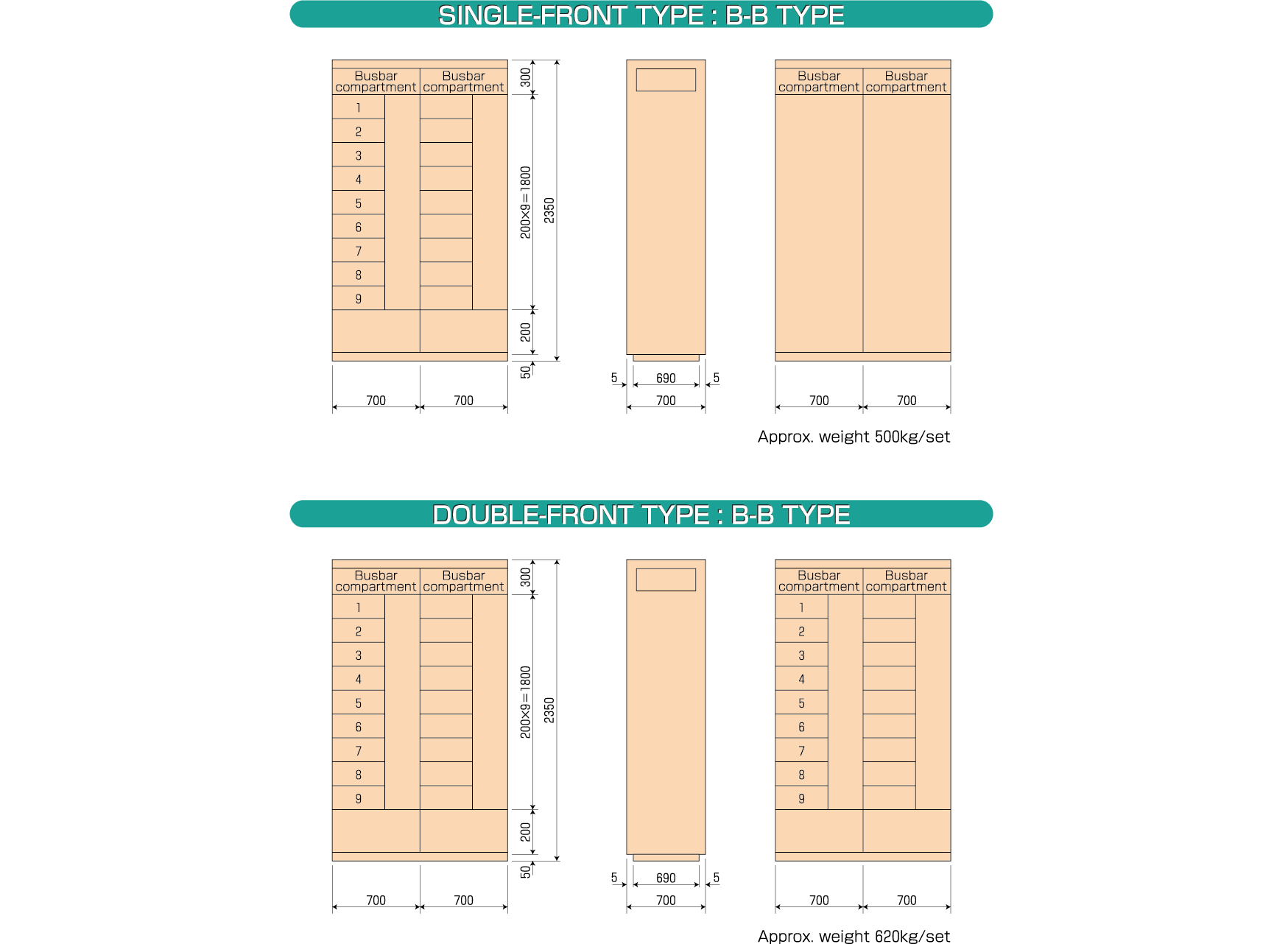
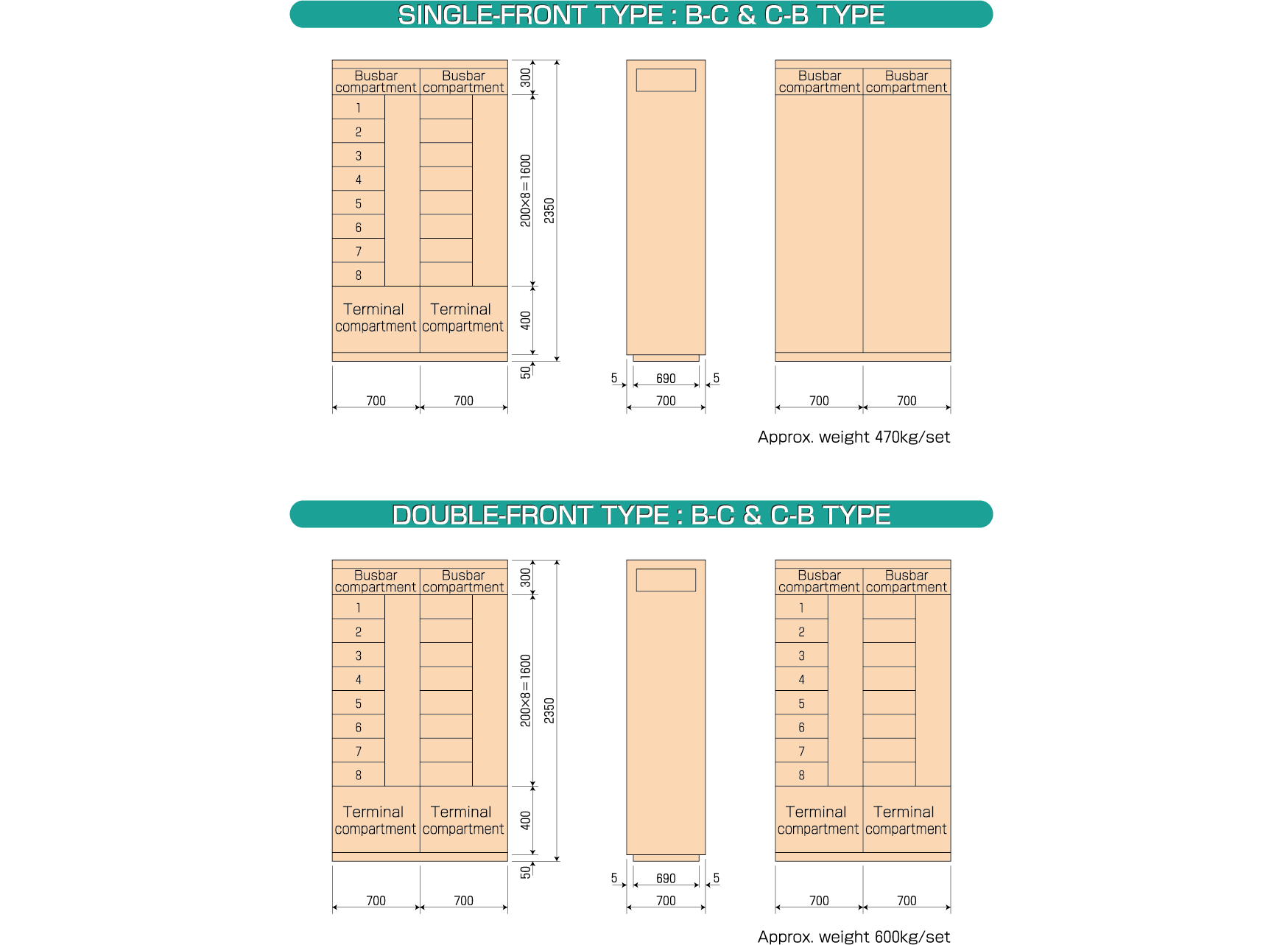
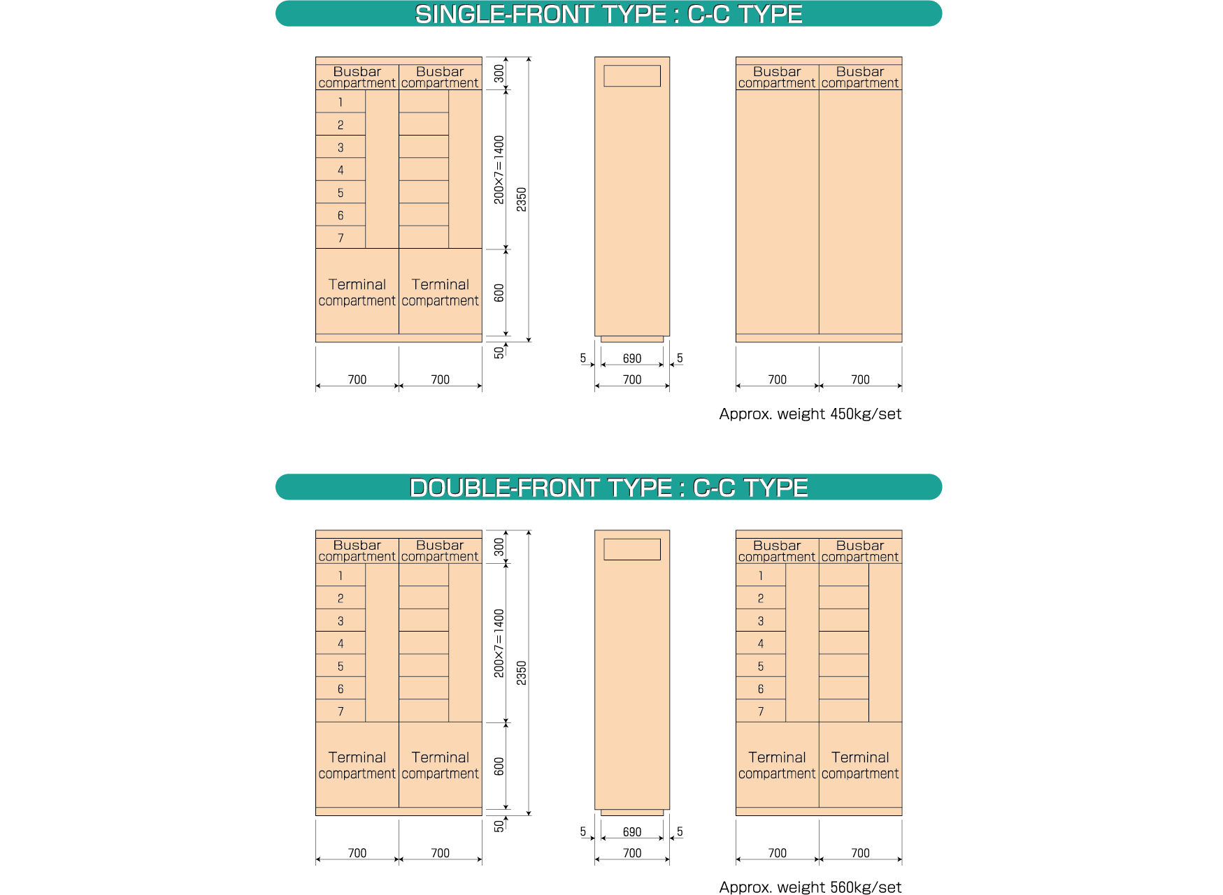
Dimensions
B-B type
B-C・C-B type
C-C type
Power supply
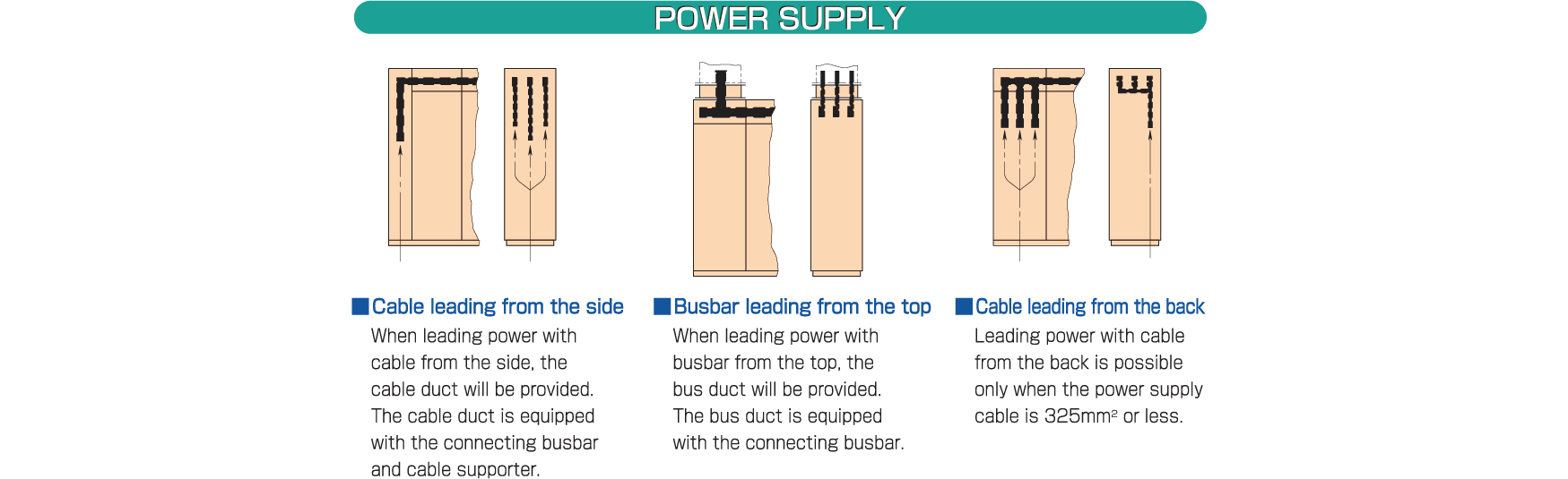
Please contact us for more details.
About multifunction relays

MFR-D1
Features
- Monitors overload, phase loss, ground, overcurrent protection, pre-alarm (overload, ground), MC (magnetic connector), congestion detector, and answer-back signal to detect unintended operation stoppages and greatly improve protective functions.
- Load current, leaked current, malfunction trip current, malfunction code, settings values, operation history data are displayed on screen. Monitor mode LED and unit display for easy understanding.
- Select optimal pattern from among 256 sequences. Enables flexible options for diverse external input signals. Able to select settings for reboot after instantaneous power failure, error output, and transmission error operation pattern, enabling diverse sequence control.
- Models available for standard networks (DeviceNet, CC-Link), and it is possible to build diverse networks for a range of systems, from small-scale to large-scale systems.
- Input (fixed 3-points, maximum 8 points), output (fixed 2-points, maximum 5 points), analog input/output (1 point each), enabling you to freely select functions for selected input/output. Maximum number of selected input/outputs will change depending on the control method.
- Includes available power (kW) and available capacity (kWh) measurement function that can be used for energy conservation monitoring.
※ In accordance with Measurement Act Article 16, this unit cannot be used on feed-in transactions or distribution. - Configured data and history data is saved in nonvolatile memory and is not lost in the event of a long-term power outage.
- Display panel includes a protective cover to prevent unintended operations.
Specifications
-
- Control power supply (standard)
- 100 VAC (85 to 132 VAC)
-
- Inrush current
- Max. 20 A, not to exceed 3 ms (100 VAC, 50 Hz)
-
- Power consumption
- Max. 8 VA (excluding input/output load)
-
- Rated frequency
- 50/60 Hz (selectable by setting)
-
- Insulation resistance
- 10 MΩ or more between all electrical circuits and ground
-
- Dielectric strength
- 2 kVAC for 1minute between live parts and ground
Excluding communication lines, CT, ZCT, and analog input/output terminals
-
- Ambient temperatures
- −10 °C to +55 °C(no freezing)
-
- Storage temperatures
- −20 °C to +70 °C(no freezing or condensation)
-
- Relative humidity
- 20%RH to 90%RH(no condensation)
-
- Atmosphere
- No corrosive gas or excessive dust
-
- Grounding
- Class D grounding (100 Ω or less)
-
- Weight
- Approx. 470 g (MFR-D1-C), approx. 430 g (MFR-D1-D)
-
- Allowable duration of instantaneous power failures
- 20 ms (operation continues)
-
- Noise resistance
(damped oscillatory noise) - 1 MHz to 1.5 MHz with current corresponding to 95% of set current, damped oscillatory
voltage with peak voltage of 2.5 kV to 3 kV applied for 2 seconds
* Control power supply unit, output unit
- Noise resistance
-
- Noise resistance
(high-frequency noise) - Rectangular wave impulse noise with peak voltage of 2.0 kV (1 ns/1 μs, 100 ns, 10 minutes)
* Control power supply unit, I/O unit
- Noise resistance
-
- Electrostatic noise resistance
(front panel section) - Metal contacts: ±8 kV
Panel surface (non-metallic contacts): ±15 kV
- Electrostatic noise resistance
-
- Radio frequency noise
- Frequency bands: 50 MHz/144 MHz/430 MHz,5 W;
1,200 MHz,1 W
-
- Lightning impulse
- 4.5 kV (1.2/50 μs) between control power supply and ground
-
- Distortion wave resistance
- No malfunction or improper display when 95% of set current is applied, containing 30% fifth harmonic relative to fundamental wave
-
- Overload capacity
- Current input unit: 20 times rated secondary current of three-phase auxiliary CT for 2 seconds, twice
-
- Input/output connection method
- Connector type Compatible wires: Wire core size AWG 24 to 18, Max. sheath diameter: 3.1 mm
-
- Applicable standards
- JEM 1356:1994 Thermal and electronic protective relays for motors
JEM 1357:1995 Static protective relays for motors
Protection Functions
Protection Function Specifications
Item Specifications* Operating value Operating time Overload protection (OL) Fixed at 115% of set current value 2 s to 64 s, lock Phase loss protection (SP) 40%/60%, lock Fixed at 2.0 s Overcurrent protection (OCI) 110% to 600%, lock 0.2 s to 9.0 s Undercurrent protection (UC) 30% to 80%, lock 1 s to 9.0 s Ground fault protection (OCG) 30/100/200/500 mA, lock 0.1/0.3/0.5/1.0 s Instantaneous power failure
restart relayInstantaneous failure compensation time: Lock 0.2/0.5 s to 5.0 s
Delay restart time: 0.0/0.5/1.0 s to 60 s
Instantaneous failure detection time: 0.2 s/0.04 s/nonPower supply pre-alarm 50% to 110% 1 to 15 mins Ground fault pre-alarm 30% to 60% Fixed at 10 s Ground fault alarm 15 mA/50 mA Fixed at 10 s * Each protection function can be locked by setting.
The reference values for OL, OCI, UC, and OCA are based on the set current value (code 0-2).
The set current value can be set to between 25% and 100% of the CT primary rated current.
External Serial Interface
Model Upstream interface PC loader interface MFR-D1-D DeviceNet EIA-ES-422 (standard on all models) MFR-D1-C CC-Link Communication protocol manuals are available for each interface.
Measurement and Display Specifications
Item Effective display range Display range and accuracy Load current (IL) 2.5% to CT rated value to 10 × CT rated value
Maximum phase (R/S/T phase display selectable by setting)±1.5% FS: 0, 2.5 to 125%
± 5% FS: 125 to 1,000%External analog input (Ai) Analog input 0 V to 10 V is displayed
between the configured lower and upper limits.External signal accuracy not included.
±5%FSZero-phase current (IG) 10 mA to 500 mA ±5%FS: 0, 10 to 500 mA Active power/active energy Simplified measurement method
Active power P = √3 × IL × V × pf
Where IL is the load current and voltage V is set
V = 90 V to 480 V (in 2 V increments)May differ from actual power (energy) if voltage and current fluctuate significantly.
Operational Control
Control method types
Control method Details Non-reversing circuit Allows selection of operating sequence from 256 fixed patterns.
Equipped with reversing operation interlock timerReversing circuit Open transition 2Mag Allows precise setting of star operation time, star-delta switching time, and starting resistor protection time. Open transition 3Mag Closed transition Power supply through circuit Functions as a measurement/protection relay without controlling operation. Mag, Ctt, Ans signals
b contact methodThe control method is determined automatically when the settings are changed.
Operating modes
Operating mode Panel display Effective control location Direct Direct (DIR) Operational control switches on the panel Site Remote (REM) External Di/DO signals assigned to the operational control function Central Remote (REM) Upstream controller
Input/Output Specifications
Input 3 fixed points (forward, stop, 88 Fans) Voltage on/off input 24 VDC, on voltage 15 V or higher 8 selectable points (29 variations). The maximum number of points varies depending on the selected control method. Output 2 fixed points: ① forward (MCS), ② stop/fault (trip) Maximum switching capacity: 250 VAC,5 A;24 VDC,5 A
Allowable continuous current: 1 A5 selectable points (18 variations)
The maximum number of points varies depending on the selected control method.Analog input 1 point (non-isolated), 0 to 10 VDC
Input impedance 10 kΩ or more, allowable input voltage ±40 VDCAnalog output 1 point (isolated), 4 mA to 20 mADC
Allowable load 300 Ω or less, response time 2 s or less
History Data
Operating time , number of forward operations, number of reverse operations, maximum load current, minimum load current,
number of fault operations (external trip count, OL count, SP count, OCI count, etc.), number of pre-alarms, fault history, etc.Product category- TOP
- Products
- Motor Control Center
- NH-C Type Control Center